IBM 8677 Hardware Maintenance Manual - Page 24
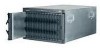
This identifies the components and indicators on the rear of your, BladeCenter unit. - compatibility
 |
UPC - 000435842312
View all IBM 8677 manuals
Add to My Manuals
Save this manual to your list of manuals |
Page 24 highlights
14 BladeCenter E Type 8677 and 1881: Hardware Maintenance Manual and Troubleshooting Guide Power module 2 Rear system LED panel AC DC Reserved module Management Power module 1 DC AC Blower module 2 Power module bay 4 Switch module 2 Switch module bay 4 Blower module 1 Power module bay 3 Rear view This section identifies the components and indicators on the rear of your BladeCenter unit. System service card Chassis Service Information Hot-Plug Processor Blade Processor Blade Operator Panel CD Hot-Plug Media Tray Operator Panel Location Information Power-on Over-temperature System error Hot-Swap Hard Disk Drives Common Chassis FRUs Switch module 1 Switch module Customer Information For More Information http://www.ibm.com/pc/support Download files, hints & tips, create custom profiles, and frequently asked questions http://www.ibm.com/eserver/xseries IBM server xSeries home page http://www.ibm.com/pc/us/compat/ Compatibility information http://www.ibm.com/pc/ww/eserver/ xseries/serverguide IBM ServerGuide home page http://www.ibm.com/servers IBM Server home page bay 3 Writeable area
-
 1
1 -
2
-
3
-
4
-
5
-
6
-
7
-
8
-
9
-
10
-
11
-
12
-
13
-
14
-
15
-
16
-
17
-
18
-
 19
19 -
 20
20 -
 21
21 -
 22
22 -
 23
23 -
 24
24 -
 25
25 -
 26
26 -
 27
27 -
 28
28 -
 29
29 -
30
-
31
-
32
-
33
-
34
-
35
-
36
-
37
-
38
-
39
-
40
-
41
-
42
-
43
-
44
-
45
-
46
-
47
-
48
-
49
-
50
-
51
-
52
-
53
-
54
-
55
-
56
-
57
-
58
-
59
-
60
-
61
-
62
-
63
-
64
-
65
-
66
-
67
-
68
-
69
-
70
-
71
-
72
-
73
-
74
-
75
-
76
-
77
-
78
-
79
-
80
-
81
-
82
-
83
-
84
-
85
-
86
-
87
-
88
-
89
-
90
-
91
-
92
-
93
-
94
-
95
-
96
-
97
-
98
-
99
-
100
-
101
-
102
-
103
-
104
-
105
-
106
-
107
-
108
-
109
-
110
-
111
-
112
-
113
-
114
-
115
-
116
-
117
-
118
-
119
-
120
-
121
-
122
-
123
-
124
-
125
-
126
-
127
-
128
-
129
-
130
-
131
-
132
-
133
-
134
-
135
-
136
-
137
-
138
-
139
-
140
-
141
-
142
-
143
-
144
-
145
-
146
-
147
-
148
-
149
-
150
 |
 |
