IBM DPSS-309170 Installation Manual - Page 7
Con the jumper settings, Option jumper blocks
 |
View all IBM DPSS-309170 manuals
Add to My Manuals
Save this manual to your list of manuals |
Page 7 highlights
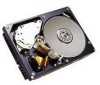
IBM storage products Ÿ Record the following information for future reference: Drive model Drive part number Drive serial number Date of purchase Place of Purchase Configure the jumper settings Option jumper blocks The drive has features that are usually enabled by the use of jumpers. A jumper is a small plasticcovered electrical conductor that connects a pair of pins on a jumper block, thereby enabling a particular function in the drive. Jumpers can be purchased at most computer stores. See the illustration below for the location of the two jumper blocks which are designated as J4 and J6. Jumper pins have a pitch of 2mm. J6 J4 +5V +5V C1onnected to 5V via Polyswitch for 68-pin and NC for 80-pin Resistor (150 Ohm) J4 J6 1 3 5 7 9 11 13 2 4 6 8 10 12 14 13 579 2 4 6 8 10 12 14 ID Bit 3 ID Bit 2 ID Bit 1 ID Bit 0 Force Mode Term power (SCSI I/F for 68-pin models NC for 80-pin models) To LED pin 8 Aux connector (68-pin models) To LED out pin 77 (80-pin models) Resistor 68-pin = 150 Ohm 80-pin = 0 Ohm To Resistor Collector Reserved Disable unit attention TI sync negotiation Disable Parity Delay start 6/12 Auto start delay Enable auto spin up (68-pin models) Disable auto spin up (80-pin models) IBM Technology Group Support Center Page 7 07N5612IG10
-
 1
1 -
 2
2 -
 3
3 -
 4
4 -
 5
5 -
 6
6 -
 7
7 -
 8
8 -
 9
9 -
 10
10 -
 11
11 -
 12
12 -
13
-
14
-
15
-
16
-
17
-
18
-
19
-
20
-
21
-
22
-
23
-
24
-
25
-
26
 |
 |
