IBM SAN04B-R User Guide - Page 33
Management, ports, Fibre, Channel, Ethernet, System, status, power, address, pull-out
 |
View all IBM SAN04B-R manuals
Add to My Manuals
Save this manual to your list of manuals |
Page 33 highlights
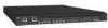
Management ports An RJ-45 serial port ( 2 in Figure 1 on page 4) and a 10/100 BaseT Ethernet port ( 3 ) are included on the router for management purposes. The serial connector is for initial IP address configuration and for recovery of the router to its factory default settings should Flash memory contents be lost. It is not intended for normal administration or maintenance functions. An RJ-45 serial cable is provided with the router for management through this serial connection. An RJ-45 to DB9 adaptor is also provided with the cable. An Ethernet cable can be used to connect the Ethernet port directly to a management workstation or to an Ethernet network that includes the management workstation. There are two LEDs on the Ethernet management port. One LED indicates link status, and the other indicates the speed (10 Mb/sec or 100 Mb/sec). See "LEDs on the port side of the router" on page 30 for more details on these LEDs. The TCP/IP address for the Ethernet management port can be configured from the serial port or directly from the Ethernet port itself. Fibre Channel ports | The standard router has two physical Fibre Channel ports ( 4 in Figure 1 on page | 4), numbered 0 and 1, that are enabled in this model. The next 14 physical ports | (2-15) can be enabled with an upgrade license. An LED next to the port number indicates the port status. See "LEDs on the port side of the router" on page 30 for more details on these LEDs. The ports support Fibre Channel Routing services with link speeds up to 1-, 2-, or 4-Gbps. The ports are able to auto-negotiate to the maximum link speed. A number of different small form-factor pluggable (SFP) optical transceivers are compatible with these ports. Contact your IBM representative for more information on SFPs for this product. Ethernet ports Two GbE ports ( 5 in Figure 1 on page 4) numbered GE0 and GE1 support the FCIP and Fibre Channel Routing Services features with link speeds up to 50 Mbps | (up to 1 Gbps with upgrade license). Each GbE port can each support one FCIP | tunnel (eight with upgrade license). Each FCIP tunnel is represented and managed as an Fibre Channel E_Port. Fibre Channel Routing Services functionality can be used over the FCIP link. Fabrics connected through FCIP merge if the ports are configured as VE_Ports, and do not merge if they are configured as VEX_Ports. If VE_Ports are used in an Fibre Channel Routing Services backbone fabric configuration, then the backbone fabric merges but the EX_Port attached to edge fabrics do not merge. For more information see the Fabric OS Administrator's Guide. System status and power LEDs Two LEDs ( 6 in Figure 1 on page 4) display an indication of the overall status of the product. The System Status LED (the top LED) provides information on the current status of the router. The System Power LED (the lower LED) indicates whether the product is on, and the status of the power supplies. See "LEDs on the port side of the router" on page 30 for more details on these LEDs. IP address, WWN pull-out tab The pull-out tab ( 7 in Figure 1 on page 4) provides a space to record the router IP address after you change it from the factory default. See "Setting the router IP address" on page 20 for instructions on setting the IP address. The tab also contains the world wide name (WWN) of the router and its serial number. Chapter 1. Introducing the SAN04B-R 5
-
 1
1 -
2
-
3
-
4
-
5
-
6
-
7
-
8
-
9
-
10
-
11
-
12
-
13
-
14
-
15
-
16
-
17
-
18
-
19
-
20
-
21
-
22
-
23
-
24
-
25
-
26
-
27
-
 28
28 -
 29
29 -
 30
30 -
 31
31 -
 32
32 -
 33
33 -
 34
34 -
 35
35 -
 36
36 -
 37
37 -
 38
38 -
39
-
40
-
41
-
42
-
43
-
44
-
45
-
46
-
47
-
48
-
49
-
50
-
51
-
52
-
53
-
54
-
55
-
56
-
57
-
58
-
59
-
60
-
61
-
62
-
63
-
64
-
65
-
66
-
67
-
68
-
69
-
70
-
71
-
72
-
73
-
74
-
75
-
76
-
77
-
78
-
79
-
80
-
81
-
82
-
83
-
84
-
85
-
86
-
87
-
88
-
89
-
90
-
91
-
92
-
93
-
94
-
95
-
96
-
97
-
98
-
99
-
100
-
101
-
102
-
103
 |
 |
