IC Realtime ICIP-D2001-IR-D-2.8 Product Manual - Page 10
Step 4, Step 5, Step 6
 |
View all IC Realtime ICIP-D2001-IR-D-2.8 manuals
Add to My Manuals
Save this manual to your list of manuals |
Page 10 highlights
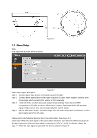
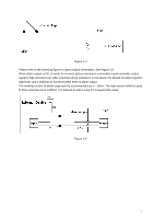
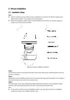
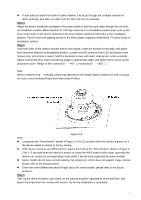
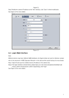
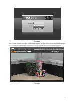
If user pulls out cable from side of cable channel, it must go through the U-shape channel on dome pedestal, and take out cable from the side exit hole on pedestal. Step 4 Adjust the device installation pedestal to the proper position and then pull cable through the exit hole on Installation surface. Make direction of TOP sign same as it on installation position map. Line up the three screw holes in the device pedestal to the three plastic expansion bolt holes in the installation position. Put the three self-tapping screws in the three plastic expansion bolts firmly. Fix dome body on installation surface. Step 5 Hold both sides of the rotation bracket bottom with hands, rotate the bracket horizontally, and adjust lens horizontal direction to designated position. Loosen one M2 screw on fixed LED decoration cover (loosen only, do not take it down), hold the decoration cover with hand, making lens rotate vertically. Adjust vertical direction of lens monitoring image to appropriate angle, and fasten the fix screw on the decoration cover. Range of lens: vertical (0°~+65°), horizontal (0°~+355°). Note: When it rotates to 64° vertically, please pay attention to the image rotation direction in order to avoid the outer cover blocking IR light and influencing IR effect. Figure 2-2 Note: Long press the "Reset button" shown in Figure 2-3 for 10 seconds when the device is power on if the device needs to restore to factory setting. If the device needs to use WPS function, please short press the "Reset button" shown in Figure 2- 2 for 1~2 seconds when the device is power on, press the WPS button of the router, generally the device can connect to corresponding router within 1 minute (only supported by some models). Some models do not have vertical rotating ring component, which does not support image rotation, please refer to the actual product. There are some differences about IR light layout for some models, please refer to the actual products. Step 6 Take up the dome enclosure, put it back on the camera properly regarding to screw and hole, and fasten the three inner hex screws with wrench. So far the installation is completed. 5
-
 1
1 -
2
-
3
-
4
-
 5
5 -
 6
6 -
 7
7 -
 8
8 -
 9
9 -
 10
10 -
 11
11 -
 12
12 -
 13
13 -
 14
14 -
 15
15
 |
 |
