IC Realtime ICIP-D2001-IR-D-2.8 Product Manual - Page 9
Device Installation
 |
View all IC Realtime ICIP-D2001-IR-D-2.8 manuals
Add to My Manuals
Save this manual to your list of manuals |
Page 9 highlights
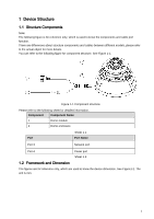
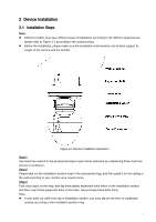
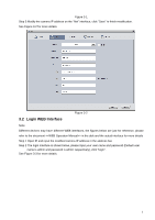
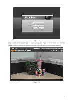
2 Device Installation 2.1 Installation Steps Note: Different models may have different ways of installation according to the different appearances, please refer to Figure 2-1 according to the actual product. Before the installation, please make sure the installation environments can at least support 3x weight of the camera and the bracket. Figure 2-1 Device installation illustration Step 1 Use inner hex wrench in the accessories bag to open dome enclosure by unfastening three inner hex screws on enclosure. Step 2 Please take out the installation position map in the accessories bag, and then paste it on the ceiling or the wall according to your monitor area requirements. Step 3 Find cross signs on the map, and dig three plastic expansion bolts holes on the installation surface and then insert three expansion bolts in the holes. Secure these three bolts firmly. Note: If user pulls out cable from top of installation surface, you must dig an exit hole on installation surface according to the installation position map. 4
-
 1
1 -
2
-
3
-
 4
4 -
 5
5 -
 6
6 -
 7
7 -
 8
8 -
 9
9 -
 10
10 -
 11
11 -
 12
12 -
 13
13 -
 14
14 -
15
 |
 |
