IC Realtime ICIP-D2001-IR-D-2.8 Product Manual - Page 7
Alarm Setup
 |
View all IC Realtime ICIP-D2001-IR-D-2.8 manuals
Add to My Manuals
Save this manual to your list of manuals |
Page 7 highlights
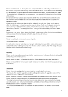
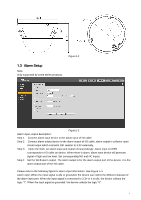
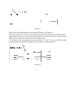
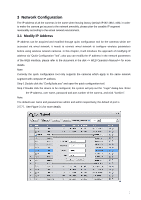
Figure1-2 1.3 Alarm Setup Note: Only supported by some series products. Figure1-3 Alarm input, output description: Step 1 Connect alarm input device to the alarm input of I/O cable. Step 2 Connect alarm output device to the alarm output of I/O cable, alarm output is collector open circuit output which connects 10K resistor to 3.3V externally. Step 3 Open the Web, set alarm input and output correspondingly. Alarm input on WEB corresponds to I/O cable on device. When there is alarm, alarm input device will generate signal of high and low level. Set corresponding NO and NC inputs. Step 4 Set the WEB alarm output. The alarm output is for the alarm output port of the device. It is the alarm output port of the I/O cable. Please refer to the following figure for alarm input information. See Figure 1-4. Alarm input: When the input signal is idle or grounded, the device can collect the different statuses of the alarm input port. When the input signal is connected to 3.3V or it is idle, the device collects the logic "1". When the input signal is grounded, the device collects the logic "0". 2
-
 1
1 -
 2
2 -
 3
3 -
 4
4 -
 5
5 -
 6
6 -
 7
7 -
 8
8 -
 9
9 -
 10
10 -
 11
11 -
 12
12 -
13
-
14
-
15
 |
 |
