IC Realtime ICIP-MLD42-IR Product Manual - Page 10
input signal is logic 0; and to NC if the alarm input signal is logic 1.
 |
View all IC Realtime ICIP-MLD42-IR manuals
Add to My Manuals
Save this manual to your list of manuals |
Page 10 highlights
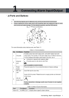
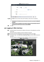
Log in web interface, and configure alarm input and alarm output in alarm setting. The alarm input in the web interface is corresponding to the alarm input end of the I/O port. There will be high level and low level alarm signal generated by the alarm input device when alarm occurs, set the input mode to "NO" (default) if the alarm input signal is logic "0"; and to "NC" if the alarm input signal is logic "1." The alarm output in the web interface is corresponding to the alarm output end of the device, which is also alarm output end of the I/O port. Connecting Alarm Input/Output 3
-
 1
1 -
2
-
3
-
4
-
 5
5 -
 6
6 -
 7
7 -
 8
8 -
 9
9 -
 10
10 -
 11
11 -
 12
12 -
 13
13 -
 14
14 -
 15
15 -
16
-
17
-
18
-
19
-
20
 |
 |

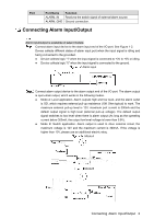
Connecting Alarm Input/Output
3
Log in web interface, and configure alarm input and alarm output in alarm setting.
The alarm input in the web interface is corresponding to the alarm input end of the
I/O port. There will be high level and low level alarm signal generated by the alarm
input device when alarm occurs, set the input mode to "NO" (default) if the alarm
input signal is logic "0"; and to "NC" if the alarm input signal is logic "1."
The alarm output in the web interface is corresponding to the alarm output end of
the device, which is also alarm output end of the I/O port.