Icom GM800 Instruction Manual - Page 7
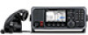
PANEL DESCRIPTION, ■ Main unit
 |
View all Icom GM800 manuals
Add to My Manuals
Save this manual to your list of manuals |
Page 7 highlights
■ Matn unta q FERRITE EMI FILTER 2 PANEL DESCRIPTION !2 !1 FERRITE EMI FILTER Qutck Reneoence 1 2 we rt y u i o !0 3 q GROUND TERMINAL [GND] Connect to the ship's ground. (p. 81) w DSC ANTENNA CONNECTER Connect to a 50 Ω HF marine band antenna through a 50 Ω coaxial cable with a PL-259 plug. This antenna is used for receiving Distress calls. NOTE: To receive a Distress call, BE SURE to connect an HF marine band antenna to this antenna connector. Otherwise, you cannot receive any Distress calls. e SPEAKER JACK [SP] Connect to the SP-24 (p. 80) or an external speaker. NOTE: When using an external speaker, BE SURE to turn OFF the internal speaker. (p. 5) Audio is output from the external speaker only when the internal speaker is OFF. r GPS JACK [GPS] Connect to a GPS receiver to input position and UTC data for DSC operations. (IEC 61162-1 Edition 4.0 (2010-11)) • An IEC 61162-1 Edition 4.0 (2010-11) (sentence formatters: GGA) compatible GPS receiver is required. Ask your dealer about suitable GPS receivers. GPS IN (+) RCA GPS IN (-) t CONTROLLER CONNECTOR [CONTROLLER] Connect to the supplied controller. y MODEM SOCKET [AF/MOD] (p. 87) 4 Connect to an external terminal unit for SSB mode operation through an RS-232C cable (D-sub 15-pin). 5 u REMOTE SOCKET [REMOTE] (p. 88) 6 Connect to a PC through an RS-232C cable (D-sub 9-pin) for remote control. 7 i PRINTER CONNECTOR Connect to an IBM® centronics or compatible printer to automatically or manually print out 8 received DSC information. 9 o ANTENNA CONNECTOR Connect to a wire or whip antenna through the AT-141 hf automatic antenna tuner. The 10 antenna is used for transmitting any calls and receiving any calls other than Distress calls. 11 RWARNING! NEVER directly connect the antenna to this connector. 12 !0 TUNER CONTROL SOCKET [TUNE] Connect to the control cable of the supplied AT-141 hf automatic antenna tuner. A female connector kit is supplied to connect the AT-141. !1 POWER SWITCH [DC ISOLATE] Turns the transceiver's main power ON or OFF. When the main power is ON, the power key's backlight is dimly lit. !2 DC POWER TERMINALS Connect to a 24 V DC power source through the supplied DC power cables. The red terminal is positive (+) and the black terminal is negative (-). 13 14 15 16 17 2
-
 1
1 -
 2
2 -
 3
3 -
 4
4 -
 5
5 -
 6
6 -
 7
7 -
 8
8 -
 9
9 -
 10
10 -
 11
11 -
 12
12 -
13
-
14
-
15
-
16
-
17
-
18
-
19
-
20
-
21
-
22
-
23
-
24
-
25
-
26
-
27
-
28
-
29
-
30
-
31
-
32
-
33
-
34
-
35
-
36
-
37
-
38
-
39
-
40
-
41
-
42
-
43
-
44
-
45
-
46
-
47
-
48
-
49
-
50
-
51
-
52
-
53
-
54
-
55
-
56
-
57
-
58
-
59
-
60
-
61
-
62
-
63
-
64
-
65
-
66
-
67
-
68
-
69
-
70
-
71
-
72
-
73
-
74
-
75
-
76
-
77
-
78
-
79
-
80
-
81
-
82
-
83
-
84
-
85
-
86
-
87
-
88
-
89
-
90
-
91
-
92
-
93
-
94
-
95
-
96
-
97
-
98
-
99
-
100
 |
 |
