Icom IC-M24 Instruction Manual - Page 12
PANEL DESCRIPTION, ■ Front, top and side panels
 |
View all Icom IC-M24 manuals
Add to My Manuals
Save this manual to your list of manuals |
Page 12 highlights
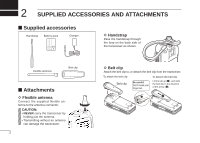
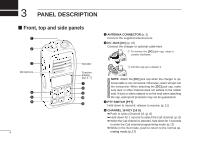
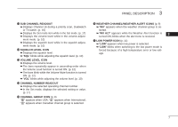
3 PANEL DESCRIPTION ■ Front, top and side panels q w e Microphone r t y Speaker Function display (pp. 6, 7) u i o !0 !1 4 q ANTENNA CONNECTOR (p. 2) Connect the supplied antenna here. w DC JACK [DC] (p. 23) Connect the charger or optional cable here. q To remove the [DC] jack cap, rotate it counter clockwise. w Pull the cap up to detach it. NOTE: Attach the [DC] jack cap when the charger or optional cable is not connected. Otherwise, water will get into the transceiver. When attaching the [DC] jack cap, make sure dust or other material does not adhere to the rubber seal. If dust or other material is on the seal when attaching the cap, waterproof protection may not be guaranteed. e PTT SWITCH [PTT] Hold down to transmit; release to receive. (p. 11) r CHANNEL 16 KEY [16 9] ➥ Push to select Channel 16. (p. 8) ➥ Hold down for 1 second to select the Call channel. (p. 8) ➥ When the Call channel is selected, hold down for 3 seconds to enter the Call channel programming mode. (p. 12) ➥ While in the Set mode, push to return to the normal operating mode. (p. 17)
-
 1
1 -
2
-
3
-
4
-
5
-
6
-
 7
7 -
 8
8 -
 9
9 -
 10
10 -
 11
11 -
 12
12 -
 13
13 -
 14
14 -
 15
15 -
 16
16 -
 17
17 -
18
-
19
-
20
-
21
-
22
-
23
-
24
-
25
-
26
-
27
-
28
-
29
-
30
-
31
-
32
-
33
-
34
-
35
-
36
-
37
-
38
-
39
-
40
 |
 |
