Icom IC-R20 Service Manual - Page 50
LOGIC unit (top), The combination of this and the next shows
 |
View all Icom IC-R20 manuals
Add to My Manuals
Save this manual to your list of manuals |
Page 50 highlights
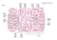
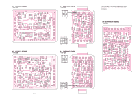
9-2 LOGIC UNIT • TOP VIEW to RF UNIT J1 20 1 LD2 +3S GND B_VCO2 B_VCO3 B_VCO4 PLLCK PLLDATA STR2 HFC B1C B2C B3C D CLK LD1 EAR A_VCO1 A_VCO2 GND B_DET B_R3V GND B_NOISE B_RSSI +3V GND PLLBSTB PLLDSTB VP GND PLLESTB PLLCSTB PLLASTB RFO A_DET A_R3V GND A_NOISE A_RSSI 21 J5 40 A DIAL LCD J9 to REC UNIT J6 1 AOUT A_ATN B_ATN 4 GND HJ8 B DIAL J3 EXT SP/CI-V from the external speaker J6 DC from the external DC power supply HJ9 1 GND SUB_3C VOL_UP_DOWN SQL TXD 6 RXD to REC UNIT J7 9 - 3 The combination of this page and the next page shows the unit layout in the same configuration as the actual P.C. Board. Li-ion Battery - + CP2 CP1 CP4 CP3
-
 1
1 -
2
-
3
-
4
-
5
-
6
-
7
-
8
-
9
-
10
-
11
-
12
-
13
-
14
-
15
-
16
-
17
-
18
-
19
-
20
-
21
-
22
-
23
-
24
-
25
-
26
-
27
-
28
-
29
-
30
-
31
-
32
-
33
-
34
-
35
-
36
-
37
-
38
-
39
-
40
-
41
-
42
-
43
-
44
-
 45
45 -
 46
46 -
 47
47 -
 48
48 -
 49
49 -
 50
50 -
 51
51 -
 52
52 -
 53
53 -
 54
54 -
 55
55 -
56
-
57
-
58
-
59
-
60
-
61
-
62
-
63
-
64
-
65
-
66
-
67
-
68
-
69
-
70
 |
 |

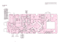
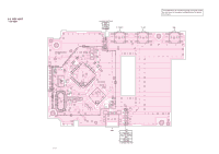
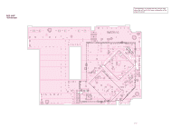
9 - 3
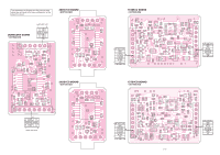
The combination of this page and the next page shows
the unit layout in the same configuration as the actual
P.C. Board.
GND
SUB_3C
VOL_UP_DOWN
SQL
TXD
RXD
1
6
to REC UNIT J7
HJ9
J9
DC
from the external
DC power supply
J6
J3
B DIAL
A DIAL
AOUT
A_ATN
B_ATN
GND
1
4
to REC UNIT J6
HJ8
CP2
CP4
CP1
CP3
Li-ion Battery
EXT SP/CI-V
from the
external speaker
LCD
J5
1
40
20
21
LD2
+3S
GND
B_VCO2
B_VCO3
B_VCO4
PLLCK
PLLDATA
STR2
HFC
B1C
B2C
B3C
D
CLK
LD1
EAR
A_VCO1
A_VCO2
GND
B_DET
B_R3V
GND
B_NOISE
B_RSSI
+3V
GND
PLLBSTB
PLLDSTB
VP
GND
PLLESTB
PLLCSTB
PLLASTB
RFO
A_DET
A_R3V
GND
A_NOISE
A_RSSI
to RF UNIT J1
+
–
9-2
LOGIC UNIT
• TOP VIEW