Icom IC-R20 Service Manual - Page 9
Circuit description, Receiver circuits
 |
View all Icom IC-R20 manuals
Add to My Manuals
Save this manual to your list of manuals |
Page 9 highlights
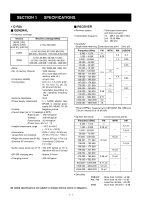
SECTION 4 CIRCUIT DESCRIPTION 4-1 RECEIVER CIRCUITS 4-1-1 BAND SWITCHING CIRCUIT (RF UNIT) The RF signals from the antenna connector pass through the limiter (D68) and an attenuator* (D69). The signals are then applied to the antenna switching circuit (D3, D11, D13, D65, D66 and D73-D75 ). *Above 2 GHz RF signals do not pass through the attenuator. 4-1-2 RF CIRCUIT (RF UNIT) The RF circuit amplifies the received signals within the range of frequency coverage and filters out-of-band signals. • A-BAND CIRCUIT (1) MF (above 0.15 MHz, below 1.9 MHz) signals RF signals (0.15-1.9 MHz) from an attenuator (D69) pass through the low-pass filter (L123-L125 and C851-C853), band switch (D66) and another low-pass filter (L88, L89, C533-C535, C657, C658). The filtered signals pass through another band switch (D67), and are then amplified at an RF amplifier (Q505). The amplified signals are applied to the next band switch (D72). (2) HF-L (above 1.9 MHz, below 15 MHz) signals RF signals (1.9-15 MHz) from an attenuator (D69) pass through the low-pass filter (L123-L125 and C851-C853), band switch (D65) and bandpass filter (L85-L87, L91, C522-C531 and C891). The filtered signals pass through another band switch (D70), and are then amplified at an RF amplifier (Q505). The amplified signals are applied to the next band switch (D72). • RF CIRCUITS from the bar antenna ANTENNA LO (1001 or 2002MHz) IC3 IC2 RF mixer 1305 3305 MHz HPF BAND SW LIMITER BPF ATT MF (0.15 1.9 MHz) ANT LPF SW LPF RF Q505 BAND SW HF-L (1.9 15 MHz) BPF BAND SW MF (15 30 MHz) HPF Q550 Pre Amp A-VHF (118 175 MHz) RF BPF Q14 B-VHF (118 175 MHz) RF BPF Q549 BAND SW 30 300M (30 300 MHz except A-VHF range) Q36 RF BAND BPF SW BAND SW A-UHF (300 470 MHz) BPF RF Q35 B-UHF (300 470 MHz) BPF RF Q548 Q551 Pre Amp 800M (470 833 MHz) LPF BAND SW BPF RF BPF Q24 1G (833 1305 MHz) IC18 RF 1st mixer IC15 RF-B circuit to 2nd mixer circuit RF Q25 BPF HPF IC19 1st mixer RF IC1 RF-A circuit to 2nd mixer circuit 4 - 1
-
 1
1 -
2
-
3
-
 4
4 -
 5
5 -
 6
6 -
 7
7 -
 8
8 -
 9
9 -
 10
10 -
 11
11 -
 12
12 -
 13
13 -
 14
14 -
15
-
16
-
17
-
18
-
19
-
20
-
21
-
22
-
23
-
24
-
25
-
26
-
27
-
28
-
29
-
30
-
31
-
32
-
33
-
34
-
35
-
36
-
37
-
38
-
39
-
40
-
41
-
42
-
43
-
44
-
45
-
46
-
47
-
48
-
49
-
50
-
51
-
52
-
53
-
54
-
55
-
56
-
57
-
58
-
59
-
60
-
61
-
62
-
63
-
64
-
65
-
66
-
67
-
68
-
69
-
70
 |
 |
