Icom ID-51A Service Manual - Page 11
St If Circuits, Vhf Band 108-174 Mhz
 |
View all Icom ID-51A manuals
Add to My Manuals
Save this manual to your list of manuals |
Page 11 highlights
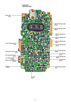
1ST IF CIRCUITS VHF BAND (108-174 MHz) • Band A (137-174 MHz) The RX signal from the RF circuit is applied to the 1st mixer (Q820) and mixed with the 1st LO signal, resulting in the 46.35 MHz 1st IF signal. The converted signal is passed through the RF SW (D820), 1st IF filter (FI3) and limiter (D23), and then applied to the 1st IF AMP. (Q44). The amplified signal is applied to the 2nd IF circuit, through the limiter (D22). • Band B (108-174 MHz) The RX signal from the RF circuit is applied to the 1st mixer (Q830) and mixed with the 1st LO signal, resulting in the 61.65 MHz 1st IF signal. The converted signal is passed through the RF SW (D830), 1st IF filter (FI880) and limiter (D880), and then applied to the 1st IF AMP. (Q901). The amplified signal is applied to the 2nd IF circuit. UHF BAND (380-479 MHz) • Band A The RX signal from the RF circuit is applied to the 1st mixer (Q801) and mixed with the 1st LO signal, resulting in the 46.35 MHz 1st IF signal. The converted signal is passed through the RF SW (D801), 1st IF filter (FI3) and limiter (D23), and then applied to the 1st IF AMP. (Q44). The amplified signal is applied to the 2nd IF circuit, through the limiter (D22). • Band B The RX signal from the RF circuit is applied to the 1st mixer (Q811) and mixed with the 1st LO signal, resulting in the 61.65 MHz 1st IF signal. The converted signal is passed through the RF SW (D811), 1st IF filter (FI880) and limiter (D880), and then applied to the 1st IF AMP. (Q901). The amplified signal is applied to the 2nd IF circuit. • 1ST IF CIRCUITS D22 To the 2nd IF circuit (Band A). LIMIT -Band A:46.35MHz- Q44 IF AMP D23 LIMIT FI3 XTAL BPF 46.35MHz VCO1 UNIT D801,D820 RF SW 1st LO D802,D821 A_LO RF SW Q820 From the RF circuit (Band A). Q801 From the RF circuit (Band B). To the 2nd IF circuit (Band B). -Band B:61.65MHz- Q901 IF AMP D880 LIMIT FI880 XTAL BPF 61.65MHz D811,D830 RF SW Q830 D812,D831 B_LO RF SW 1st LO VCO2 UNIT Q811 From the RF circuit (Band A). From the RF circuit (Band B). 4 - 2
-
 1
1 -
2
-
3
-
4
-
5
-
 6
6 -
 7
7 -
 8
8 -
 9
9 -
 10
10 -
 11
11 -
 12
12 -
 13
13 -
 14
14 -
 15
15 -
 16
16 -
17
-
18
-
19
-
20
-
21
-
22
-
23
-
24
-
25
-
26
-
27
-
28
-
29
-
30
-
31
-
32
-
33
-
34
-
35
-
36
-
37
-
38
-
39
-
40
-
41
-
42
-
43
-
44
-
45
-
46
-
47
-
48
-
49
-
50
-
51
-
52
-
53
-
54
-
55
-
56
-
57
-
58
-
59
-
60
 |
 |
