Image Fitness 3.01995 Bench English Manual - Page 6
Stabilizer
 |
View all Image Fitness 3.01995 Bench manuals
Add to My Manuals
Save this manual to your list of manuals |
Page 6 highlights
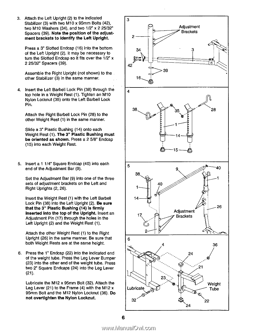
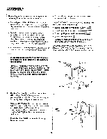
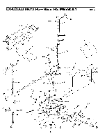
3. Attach the Left Upright (2) to the indicated Stabilizer (3) with two M10 x 95mm Bolts (42), two M10 Washers (34), and two 1/2" x 2 25/32" Spacers (39). Note the position of the adjustment brackets to identify the Left Upright. Press a 3" Slotted Endcap (16) into the bottom of the Left Upright (2). It may be necessary to turn the Slotted Endcap so it fits over the 1/2" x 2 25/32" Spacers (39). Assemble the Right Upright (not shown) to the other Stabilizer (3) in the same manner. 4. Insert the Left Barbell Lock Pin (38) through the top hole in a Weight Rest (1). Tighten an M10 Nylon Locknut (35) onto the Left Barbell Lock Pin. Attach the Right Barbell Lock Pin (28) to the other Weight Rest (1) in the same manner. Slide a 3" Plastic Bushing (14) onto each Weight Rest (1). The 3" Plastic Bushing must be oriented as shown. Press a 2 5/8" Endcap (15) into each Weight Rest. 3 2 34 42 16 4 38 Adjustment Brackets 3 39 - • 35 1 14 6-15-6 , 28 5. Insert a 1 1/4" Square Endcap (40) into each end of the Adjustment Bar (9). Set the Adjustment Bar (9) into one of the three sets of adjustment brackets on the Left and Right Uprights (2, 26). Insert the Weight Rest (1) with the Left Barbell Lock Pin (38) into the Left Upright (2). Be sure that the 3" Plastic Bushing (14) is firmly Inserted Into the top of the Upright. Insert an Adjustment Pin (17) through the holes in the Left Upright (2) and the Weight Rest (1). Attach the other Weight Rest (1) to the Right Upright (26) in the same manner. Be sure that both Weight Rests are at the same height. 6. Press the 1" Endcap (22) into the indicated end of the weight tube. Press the Leg Lever Bumper (23) into the other end of the weight tube. Press two 2" Square Endcaps (24) into the Leg Lever (21). Lubricate the M12 x 95mm Bolt (32). Attach the Leg Lever (21) to the Frame (4) with the M12 x 95mm Bolt and the M12 Nylon Locknut (36). Do not overtighten the Nylon Locknut. 5 38 1 14 17 9 40 . 40 1 26 Adjustment Brackets 2 6 4 - ,-----„, c, ,z Lubricate 23 2:- ,--- _ - o - 36 24 _ - 21 - Weight Tube 32 22 24 6
-
 1
1 -
 2
2 -
 3
3 -
 4
4 -
 5
5 -
 6
6 -
 7
7 -
 8
8 -
 9
9 -
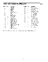 10
10 -
 11
11 -
 12
12 -
13
-
14
-
15
-
16
 |
 |