Image Fitness 760 Treadmill English Manual - Page 8
Sole May Be Damaged When The Power Is
 |
View all Image Fitness 760 Treadmill manuals
Add to My Manuals
Save this manual to your list of manuals |
Page 8 highlights
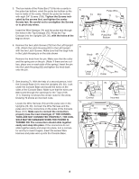
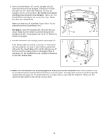
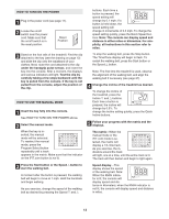
5. The box inside of the Pulse Bar (71) fits into a cavity in the pulse bar bottom; orient the pulse bar bottom so the box is inside of the cavity. Attach the pulse bar bottom with eight 3/4" Screws (108). Tighten the Screws indicated by the arrows first, and tighten the center Screws last. Be careful not to overtighten the Screws or to pinch any wires. Insert the Wire Harness (74) and the pulse wire through the holes in the Top Endcaps (75). Press the Top Endcaps into the Uprights (29, 30), with the holes at the top as shown. 6. Remove the two Latch Screws (79) from the Left Upright (29). Attach the Latch Housing (82) to the Left Upright with the two Latch Screws. Make sure that the large hole in the Latch Housing is on the side shown Remove the knob from the pin. Make sure that the collar and the spring are on the pin. (Note: If there are two collars, place one on each side of the spring.) Insert the pin into the Latch Housing (82) and tighten the knob back onto the pin. 5 Pulse Wire 74 Box 71 75 75 108 108 Pulse Bar 108 30 Bottom 29 6 Knob 29 82 79 Large Hole Spring Pin Collar 7. See drawing 7c. With the help of a second person, hold the Console Base (101) near the Uprights (29, 30). Look under the Console Base and locate the wires on the sides of the Console Base. Make sure that the wires are not routed through the openings for the Trays (109, 111). Drawing 7a shows the correct route for the wires. Drawing 7b shows an incorrect route. Locate the Wire Harness (74) and the pulse wire in the Uprights (29, 30). Connect the Wire Harness and the pulse wire to the connectors on the sides of the Console Base (101). Make sure to connect the connectors properly (see the inset drawings). IF THE CONNECTORS ARE NOT CONNECTED PROPERLY, THE CONSOLE MAY BE DAMAGED WHEN THE POWER IS TURNED ON. The connectors should slide together easily and snap into place. If the connectors do not slide together easily and snap into place, turn a connector and try to insert it again. Insert the excess Wire Harness and pulse wire up into the Console Base. 7a 7b Correct 7c 111 Incorrect 109 101 74 30 29 Pulse 74 Wire 8
-
 1
1 -
2
-
 3
3 -
 4
4 -
 5
5 -
 6
6 -
 7
7 -
 8
8 -
 9
9 -
 10
10 -
 11
11 -
 12
12 -
 13
13 -
14
-
15
-
16
-
17
-
18
-
19
-
20
-
21
-
22
-
23
-
24
-
25
-
26
-
27
-
28
-
29
-
30
-
31
-
32
-
33
-
34
 |
 |
