Image Fitness 777 English Manual - Page 10
Model
 |
View all Image Fitness 777 manuals
Add to My Manuals
Save this manual to your list of manuals |
Page 10 highlights
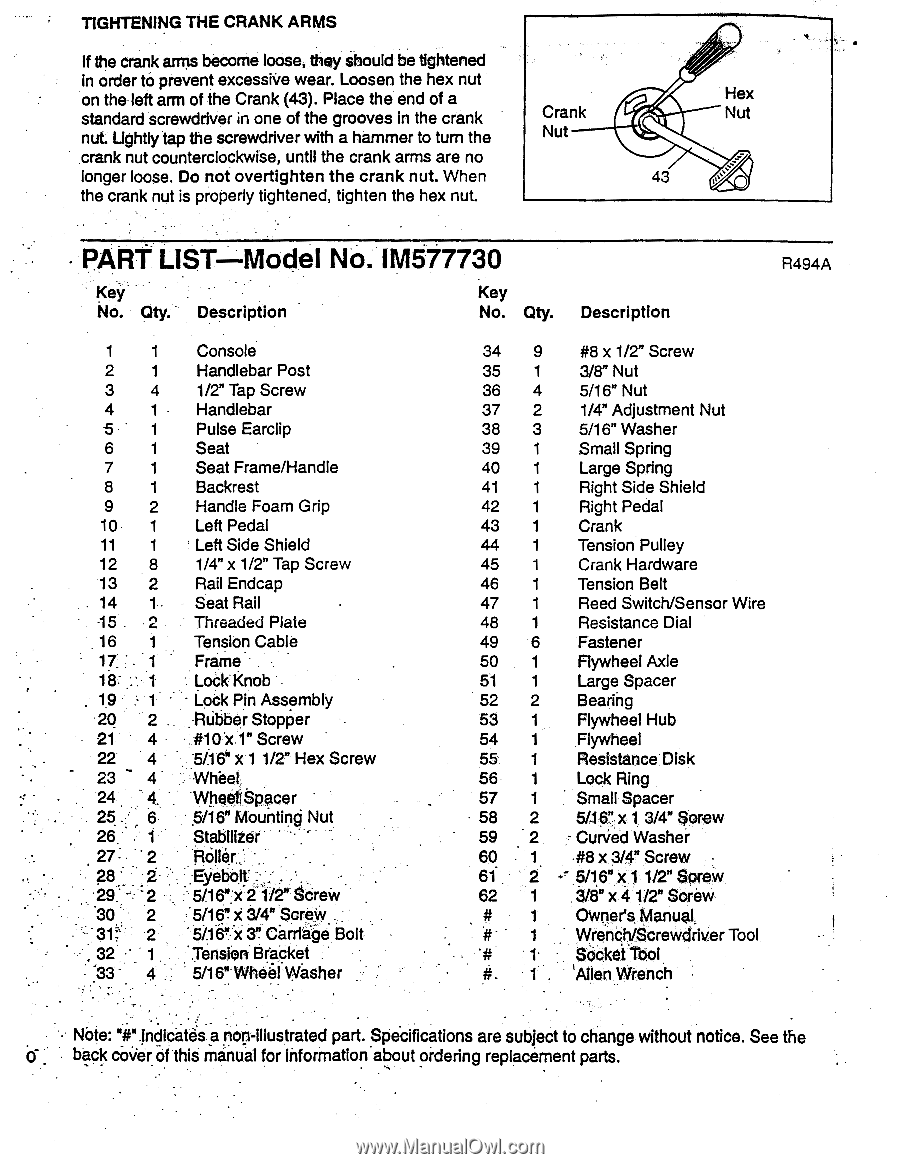
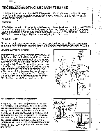
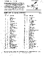
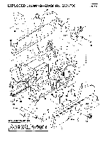
TIGHTENING THE CRANK ARMS If the crank arms become loose, they should be tightened in order to prevent excessive wear. Loosen the hex nut on the left arm of the Crank (43). Place the end of a standard screwdriver in one of the grooves in the crank nut. Lightly tap the screwdriver with a hammer to turn the crank nut counterclockwise, until the crank arms are no longer loose. Do not overtighten the crank nut. When the crank nut is properly tightened, tighten the hex nut. Crank Nut Hex Nut 43 loss • PART UST Model No, IM577730 Key No. Qty. Description Key No. Qty. Description R494A 1 1 2 1 3 4 4 1 5 1 6 1 7 1 8 1 9 2 10 1 11 1 12 8 13 2 14 115 2 16 1 17 : 18: 1 19 1 2Q 2 21 4 22 4 23 4 24 - 4. 25 6 26 • 1 27- 2 28.1 2 29: - 2 30 2 31 2 32 1 • :33 - 4 Console Handlebar Post 1/2" Tap Screw Handlebar Pulse Earclip Seat Seat Frame/Handle Backrest Handle Foam Grip Left Pedal Left Side Shield 1/4" x 1/2" Tap Screw Rail Endcap Seat Rail Threaded Plate Tension Cable Frame Look Knob - Lodk Pin Assembly Rubber Stopper . #10 X 1" Screw x 5/1e 1 1/2" Hex Screw . WheeliSpacer • 5/16" Mounting Nut Stabilizer • Rolle.r... . : 5/16":x 2'1/2" Screw 5/16" x 3/4" ScroW. `5/.16":x Carrlige Bolt :Terisioni3r4ket 5/16" Wheil Wsher • 34 9 #8 x 1/2 " Screw 35 1 3/8" Nut 36 4 5/16" Nut 37 2 1/4" Adjustment Nut 38 3 5/16" Washer 39 1 Small Spring 40 1 Large Spring 41 1 Right Side Shield 42 1 Right Pedal 43 1 Crank 44 1 Tension Pulley 45 1 Crank Hardware 46 1 Tension Belt 47 1 Reed Switch/Sensor Wire 48 1 Resistance Dial 49 6 Fastener 50 1 Flywheel Axle 51 1 Large Spacer 52 2 Bearing 53 1 Flywheel Hub 54 1 Flywheel 55 1 Resistance Disk 56 1 Lock Ring 57 1 Small Spacer 58 2 5/16",x 1 3/4" Sorew 59 2 CurVed Washer 60 1. -#8 x 3/4" Screw • 61 2 5/16" xl 1/2" Sorew 62 1 3/8" x 4 1/2" Sorew # 1 Owner's Manual, # 1 VVrench/Screwdriver Tool. 1. Socket Tool 1 'Allen Wrench • Note: "i".indicate's a non-illustrated part. Specifications are subject to change without notice. See the back• cover • of this manual for information about ordering replacement parts.
-
 1
1 -
2
-
3
-
4
-
 5
5 -
 6
6 -
 7
7 -
 8
8 -
 9
9 -
 10
10 -
 11
11 -
 12
12
 |
 |