Image Fitness 777 English Manual - Page 4
caniagaiiiolts
 |
View all Image Fitness 777 manuals
Add to My Manuals
Save this manual to your list of manuals |
Page 4 highlights
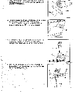
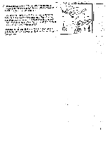
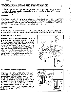
^Raul, tile: QUAMPUIM" l4.4O/ IM II its sacrum unoer me rear or the Frame (17) with the two 5/16" x.31%caniagaiiiolts (31) 17 31 2. Tighten the Right.Pedal (42) clockwise into the right arm of the Crank (43). Tighten the Left Pedal (not shown), counterclockwise into the left arm of the Crank. Each Pedal is marked with an "R" or "L" for identification. 43 / 36 26 42 3. Attach the Handlebar Post (2) to the Frame (17) with the two 5/16" x 1 1/2 " Screws (61). Be careful to avoid damaging the Sensor Wire (47) or the Tension Cable (16). 2 61 / 11 17 47 16 . 4. Attach the Handle4r (4) to the Handlebar Post (2) with the two 5116" x 1 3/4" Screw (58), Curved Washers (59), and 5/16" MOUnting Nuts (25). 4 58 _4 25 59 2
-
 1
1 -
 2
2 -
 3
3 -
 4
4 -
 5
5 -
 6
6 -
 7
7 -
 8
8 -
 9
9 -
 10
10 -
11
-
12
 |
 |

^Raul, tile:
QUAMPUIM"
l4.
4
O/
IM
II
its
sacrum
unoer
me
rear
or
the
Frame
(17)
with
the
two
5/16"
x.3
1
%caniagaiiiolts
(31)
17
/
36
2.
Tighten
the
Right.
Pedal
(42)
clockwise
into
the
right
arm
of
the
Crank
(43).
Tighten
the
Left
Pedal
(not
shown),
counterclockwise
into
the
left
arm
of
the
Crank.
Each
Pedal
is
marked
with
an
"R"
or
"L"
for
identification.
3.
Attach
the
Handlebar
Post
(2)
to
the
Frame
(17)
with
the
two
5/16"
x
1
1/2
"
Screws
(61).
Be
careful
to
avoid
damaging
the
Sensor
Wire
(47)
or
the
Tension
Cable
(16).
.
4.
Attach
the
Handle4r
(4)
to
the
Handlebar
Post
(2)
with
the
two
5116"
x
1
3/4"
Screw
(58),
Curved
Washers
(59),
and
5/16"
MOUnting
Nuts
(25).
_4
31
26
43
42
2
61
/
11
47
16
17
4
58
2
25
59