Image Fitness 777 English Manual - Page 9
Trouble, Shooting, Maintenance
 |
View all Image Fitness 777 manuals
Add to My Manuals
Save this manual to your list of manuals |
Page 9 highlights
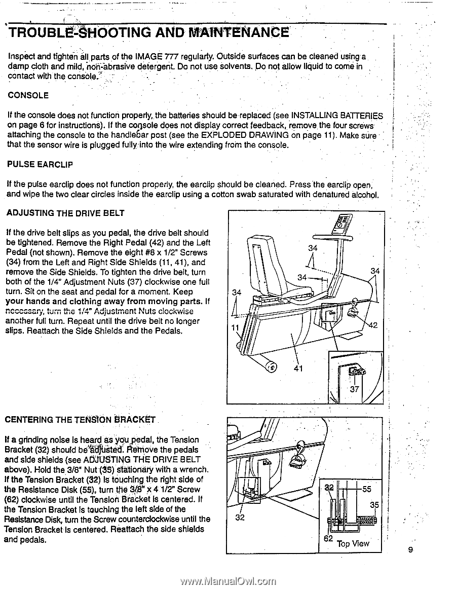
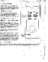
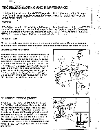
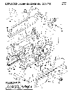
'TROUBLE-SHOOTING AND MAINTENANCE Inspect and tighten all parts of the IMAGE 777 regularly. Outside surfaces can be cleaned using a damp cloth and mild, non=abrasive detergent. Do not use solvents. Do not allow liquid to come in contact with.the console.' CONSOLE If the console does not function properly, the batteries should be replaced (see INSTALLING BATTERIES on page 6 for instructions). If the console does not display correct feedback, remove the four screws attaching the console to the handle6ar post (see the EXPLODED DRAWING on page 11). Make sure • that the sensor wire is plugged fully into the wire extending from the. console. PULSE EARCLIP If the pulse earclip does not function properly, the earclip should be cleaned. Press .the earclip open; and wipe the two clear circles inside the earclip using a cotton swab saturated with denatured alcohol. ADJUSTING THE DRIVE BELT If the drive belt slips as you pedal, the drive belt should be tightened. Remove the Right Pedal (42) and the Left Pedal (not shown). Remove the eight #8 x 1/2" Screws (34) from the Left and Right Side Shields (11, 41), and remove the Side Shields. To tighten the drive belt, turn both of the 1/4" Adjustment Nuts (37) clockwise one full turn. Sit on the seat and pedal for a moment. Keep 34 your hands and clothing away from moving parts. If necessary, turn the 1/4" Adjustment Nuts clockwise another full turn. Repeat until the drive belt no longer slips. Reattach the Side Shields and the Pedals. 11 AWI • 34 34 42 ft 41 -- • 7 CENTERING THE TENSION BRACKET If a grinding noise is heard as youpedal, the Tension Bracket (32) should bevidgieted: Adfriove the pedals and side shields (see ADJUSTING THE DRIVE BELT above). Hold the,3/8" Nut (35) Stationary with a wrench. If the Tension Bracket (32) Is touching the right side of the Resistance Disk (55), turn the aigh x 4 1/2" Screw (62) clockwise until the Tension Bracket is centered. If the Tension Bracket is touching the left side of the Resistance Disk, turn the Screw counterclockwise until the 32 Tension Bracket Is centered. Reattach the side shields and pedals. 3 55 35 2 Top View 9
-
 1
1 -
2
-
3
-
 4
4 -
 5
5 -
 6
6 -
 7
7 -
 8
8 -
 9
9 -
 10
10 -
 11
11 -
 12
12
 |
 |