Image Fitness Renew 455 Spa Canadian English Manual - Page 11
Spa Shell Diagram
 |
View all Image Fitness Renew 455 Spa manuals
Add to My Manuals
Save this manual to your list of manuals |
Page 11 highlights
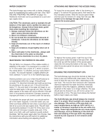
Spa Shell Diagram G C A B E D F H I J A Refer to the diagram above. The function of each component is explained below. A. The ten hydrotherapy jets provide a relaxing massage action. Three of the jets are adjustable. Note: The adjustable jets can be closed and opened by pushing and pulling the nozzles. If no air flows through the jets when the air control is turned counterclockwise, simply pull the nozzles slightly. B. The whirlpool jet directs a flow of water that creates a whirlpool action in the spa. C. The skimmer cleans the surface of the water. D. The temperature probe reads the temperature of the water. E. The underwater light can be used for night operation (see USING THE CONTROLS on page 12). F. The suction vents near the floor of the spa bring water into the pump in order to operate the system. The covers should always be in place over the suction vents. Never operate the spa without the suction covers in place. G. The air control determines the amount of air flowing through the spa jets during operation (see USING THE CONTROLS on page 12). H. The filter can be removed for cleaning or replacement (see CHECKING AND CLEANING THE FILTER on page 13). I. The console controls the spa jets, turns the underwater light on and off, and adjusts the water temperature setting (see Using the Controls on page 12). J. The diverter controls the flow of water through the hydrotherapy jets and the whirlpool jet (see USING THE CONTROLS on page 12). SECURING THE SPA COVER ON THE SPA To secure the spa cover, snap the latches on the spa cover into the buckles on the wood panels. Latch The buckles can be Key locked by inserting the key and turning it clockwise 1/4 turn. To Buckle unlock the buckles, insert the key and turn it counterclockwise 1/4 turn. Always keep the buckles locked when the spa is not in use. Keep the keys in a safe place, out of the reach of children. 11
-
 1
1 -
2
-
3
-
4
-
5
-
 6
6 -
 7
7 -
 8
8 -
 9
9 -
 10
10 -
 11
11 -
 12
12 -
 13
13 -
 14
14 -
 15
15 -
 16
16 -
17
-
18
-
19
-
20
 |
 |
