Image Fitness Renew 631 Spa User Manual - Page 8
Assembly
 |
View all Image Fitness Renew 631 Spa manuals
Add to My Manuals
Save this manual to your list of manuals |
Page 8 highlights
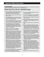
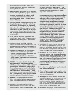
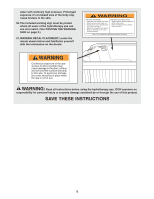
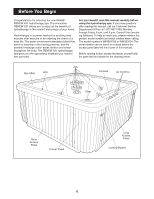
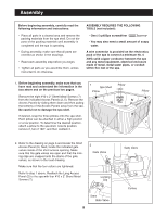
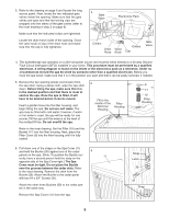
Assembly Before beginning assembly, carefully read the following information and instructions: • Place all parts in a cleared area and remove the packing materials from the spa shell. Do not dispose of the packing materials until assembly is completed and the spa is operating. • During assembly, make sure that all parts are oriented as shown in the drawings. • Read each assembly step before you begin. • Tighten all parts as you assemble them, unless instructed to do otherwise. ASSEMBLY REQUIRES THE FOLLOWING TOOLS (not included): • One (1) phillips screwdriver • You may also need a small amount of soapy water. A wire connector is provided on the electronics pack of the spa to connect a minimum No. 6 AWG solid copper conductor between the spa and any metal equipment, electrical enclosure made of metal, metal water pipes, or conduit within five feet of the spa. 1. Before beginning assembly, make sure that you have read and understand the information in the box above and on the previous two pages. Remove the eight #10 x 2" Sheet Metal Screws (7) from the indicated Access Panels (2, 5). Remove the Access Panels by sliding them down and then pulling the bottoms of the Access Panels away from the spa. Be careful not to damage the spa shell. If desired, snap the three pillows onto the spa shell. Each pillow can be attached in either a high position or a low position. To determine the desired position, attach a pillow to the spa shell, note its position, remove it, turn it 180°, and then reattach it. 1 Spa Shell Pillow 5 7 Pillow Pillow 2 7 2. Refer to the drawing on page 6 and locate the Short Access Panel (5). Next, locate the indicated gate valves inside of the short access opening. Make sure that the gate valves are open and that the locking clips are snapped onto the stems of the gate valves, as shown in the inset drawing. Make sure that the four collars are tightened. Refer to step 1 above. Reattach the Long Access Panel (2) to the spa with four #10 x 2" Sheet Metal Screws (7). 2 Gate Valve Locking Clip Stem Gate Valve 8 Gate Valve Collars
-
 1
1 -
2
-
 3
3 -
 4
4 -
 5
5 -
 6
6 -
 7
7 -
 8
8 -
 9
9 -
 10
10 -
 11
11 -
 12
12 -
 13
13 -
14
-
15
-
16
-
17
-
18
-
19
-
20
 |
 |