Image Fitness Renew 631 Spa User Manual - Page 9
Electronics Pack
 |
View all Image Fitness Renew 631 Spa manuals
Add to My Manuals
Save this manual to your list of manuals |
Page 9 highlights
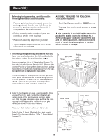
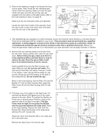
3. Refer to the drawing on page 6 and locate the long access panel. Next, locate the two indicated gate valves inside the opening. Make sure that the gate valves are open and that the locking clips are snapped onto the stems of the gate valves (refer to the inset drawing in step 2 on page 8). Make sure that the indicated collars are tightened. Locate the drain hose inside of the opening. Close the valve knob on top of the drain hose and make sure that the cap is fully tightened. 3 Gate Valve Electronics Pack Collars Drain Hose Valve Knob Collars Cap Gate Valve 4. The hydrotherapy spa operates on a 240-volt power source and must be wired directly to a 40 amp Ground Fault Circuit Interrupter (GFCI) installed in your home. This procedure must be performed by a qualified electrician. A wiring diagram is found on the inside of the electronics pack as a reference. Under no circumstances should the spa be wired by someone other than a qualified electrician. Before you have the spa wired, make sure that it is in the position you want and that it can be easily serviced, if needed. 5. Remove the two warning decals (not shown) from the spa shell. Using a damp cloth, wipe the spa shell clean. Before filling the spa, make sure that it is in the desired position and that there is room to service the spa. Once the spa is filled, it will have to be drained before it can be moved. Insert a garden hose into the filter housing, and begin filling the spa. Do not use soft water. The spa may be filled with cold water; however, if warm or hot water is used, the spa will be ready for use sooner. Fill the spa until the water is at the level of the molded fill line. Do not overfill the spa. 5 Fill to the middle of the Skimmer Housing Filter Housing 8 17 16 Filter Housing Refer to the inset drawing. Set the Filter (16) and the Basket (17) into the filter housing. Next, place the Filter Cover (8) into the filter housing until it is fully seated. 6. Pull down one of the straps on the Spa Cover (11) and hold the Buckle (30) against one of the cedar 6 panels on the spa. (Note: To position the Buckle cor- 11 rectly, have a second person hold the strap on the opposite side of the Spa Cover tight.) The Spa Cover must be tight. Do not place the Buckle over the grooves between the cedar slats. Refer to the inset drawing. Remove the latch from the Buckle (30). Attach the Buckle to the cedar panel with two #4 x 3/4" Screws (31). Attach the other three Buckles (30) to the cedar panels in the same way. Remove the Spa Cover (11) from the spa. Strap Latch 30 31 Strap 30 9
-
 1
1 -
2
-
3
-
 4
4 -
 5
5 -
 6
6 -
 7
7 -
 8
8 -
 9
9 -
 10
10 -
 11
11 -
 12
12 -
 13
13 -
 14
14 -
15
-
16
-
17
-
18
-
19
-
20
 |
 |
