Insignia NS-HT51 User Manual (English) - Page 8
Component, Description - subwoofer
 |
UPC - 600603116636
View all Insignia NS-HT51 manuals
Add to My Manuals
Save this manual to your list of manuals |
Page 8 highlights
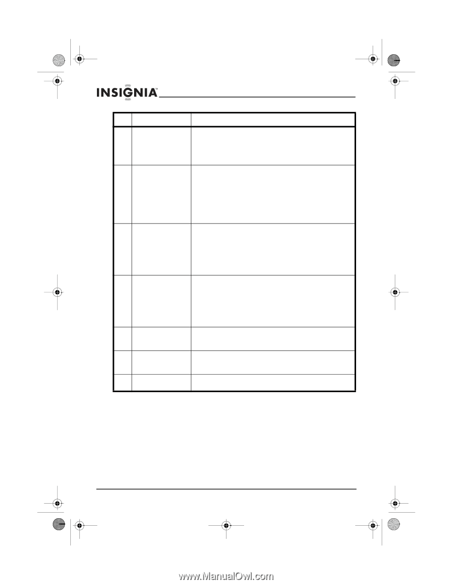
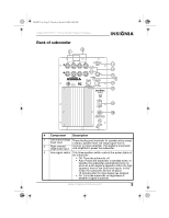
NS-HT51.fm Page 6 Thursday, March 6, 2008 6:46 AM Insignia NS-HT51 5.1 Home Theater Speaker Package # Component Description 4 Line level input These RCA jacks accept a line-level, full-range signal from the pre-amplifier or LFE output of a receiver or preamplifier. This full-range signal is processed and amplified to power the subwoofer. 5 Polarity switch This two-position switch allows the best match of acoustic output between the subwoofer and the satellite speakers in the crossover frequency region between them. • The 0° position maintains phase from input to output. • The 180° position changes the polarity by 180°. Try both settings and pick the one that sounds best. 6 Status LED This shows the status of the subwoofer. • Red indicates that the amplifier is plugged in and the power switch is either off or in standby mode with no input signal present. • Green indicates that the amplifier is operating with a signal present at the input from the pre-amplifier, receiver, or power amplifier. 7 Subwoofer crossover (frequency) This rotary control sets the upper frequency at which the output of the subwoofer begins to roll off. Continuously variable from 60 Hz to 160 Hz, it matches the upper frequency characteristics of the subwoofer to the low-frequency response of the satellite speakers. Recommended setting: 150 Hz. 8 Volume control This rotary control adjusts the level of the subwoofer (gain) and is used to balance its volume with that of the satellite speakers. 9 Main power switch This switch controls the overall power status of the subwoofer. It must be in the ON position for the subwoofer to operate. 10 Fuse For continued protection, replace the fuse with the same type and size listed. 6 www.insignia-products.com
-
 1
1 -
2
-
 3
3 -
 4
4 -
 5
5 -
 6
6 -
 7
7 -
 8
8 -
 9
9 -
 10
10 -
 11
11 -
 12
12 -
 13
13 -
14
-
15
-
16
-
17
-
18
-
19
-
20
-
21
-
22
-
23
-
24
-
25
-
26
-
27
-
28
-
29
-
30
-
31
-
32
-
33
-
34
-
35
-
36
-
37
-
38
-
39
-
40
-
41
-
42
-
43
-
44
-
45
-
46
-
47
-
48
-
49
-
50
-
51
-
52
 |
 |