Intel BLKD101GGCL Product Specification - Page 16
ATI Radeon, Xpress 200 Chipset - drivers
 |
View all Intel BLKD101GGCL manuals
Add to My Manuals
Save this manual to your list of manuals |
Page 16 highlights
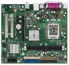
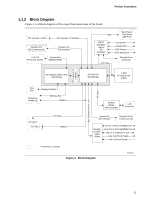
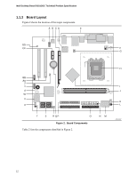
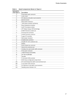
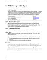
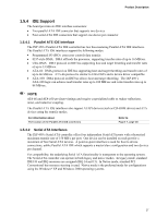
Intel Desktop Board D101GGC Technical Product Specification 1.5 ATI Radeon* Xpress 200 Chipset The ATI Radeon Xpress 200 chipset consists of the following devices: • ATI Radeon Xpress 200 Northbridge • IXP 450 Southbridge The ATI Radeon Xpress 200 Northbridge is a centralized controller for the system bus, the memory bus, and the PCI Express bus. The ATI Radeon Xpress 200 Northbridge also provides integrated graphics capabilities supporting 3D, 2D and display capabilities. The IXP 450 is a centralized controller for the board's I/O paths. The FWH provides the nonvolatile storage of the BIOS. For information about The ATI Radeon Xpress 200 Northbridge The IXP 450 Southbridge Resources used by the chipset Refer to http://www.ati.com/ http://www.ati.com/ Chapter 2 1.5.1 Graphics Subsystem The board contains two separate, mutually exclusive graphics options. Either the integrated graphics processor (contained within the ATI Radeon Xpress 200 Northbridge) is used, or a PCI Express x16 add-in card can be used. When a PCI Express x16 add-in card is installed, the ATI Radeon Xpress 200 Northbridge graphics controller is disabled. 1.5.2 Firmware Hub (FWH) The Firmware Hub provides the nonvolatile storage of the AwardBIOS for Intel. 1.5.3 USB The board supports up to eight USB 2.0 ports, supports UHCI and EHCI, and uses UHCI- and EHCI-compatible drivers. The IXP 450 Southbridge provides the USB controller for all ports. The port arrangement is as follows: • Four ports are implemented with dual stacked back panel connectors adjacent to the audio connectors • Four ports are routed to two separate front panel USB connectors NOTE Computer systems that have an unshielded cable attached to a USB port may not meet FCC Class B requirements, even if no device is attached to the cable. Use shielded cable that meets the requirements for full-speed devices. For information about The location of the USB connectors on the back panel The location of the front panel USB connectors Refer to Figure 6, page 37 Figure 7, page 38 16
-
 1
1 -
2
-
3
-
4
-
5
-
6
-
7
-
8
-
9
-
10
-
 11
11 -
 12
12 -
 13
13 -
 14
14 -
 15
15 -
 16
16 -
 17
17 -
 18
18 -
 19
19 -
 20
20 -
 21
21 -
22
-
23
-
24
-
25
-
26
-
27
-
28
-
29
-
30
-
31
-
32
-
33
-
34
-
35
-
36
-
37
-
38
-
39
-
40
-
41
-
42
-
43
-
44
-
45
-
46
-
47
-
48
-
49
-
50
-
51
-
52
-
53
-
54
-
55
-
56
-
57
-
58
-
59
-
60
-
61
-
62
-
63
-
64
-
65
-
66
-
67
-
68
-
69
-
70
-
71
-
72
-
73
-
74
 |
 |