Intel BLKD101GGCL Product Specification - Page 37
Back Panel Connectors
 |
View all Intel BLKD101GGCL manuals
Add to My Manuals
Save this manual to your list of manuals |
Page 37 highlights
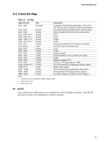
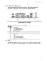
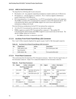
Technical Reference 2.7.1 Back Panel Connectors Figure 6 shows the location of the back panel connectors. The back panel connectors are color-coded. The figure legend (Table 15) lists the colors used (when applicable). AB C G I D E F Figure 6. Back Panel Connectors HJ OM18248 Table 15. Back Panel Connectors Shown in Figure 6 Item/callout from Figure 6 Description A PS/2 mouse port (Green) B PS/2 keyboard port (Purple) C Parallel port (Burgundy) D Serial port A (Teal) E VGA port F USB ports [4] G LAN H Line in or Rear Left/Right Out I Line out or Front Left/Right Out J Mic in or Center/LFE (Subwoofer) Out NOTE The back panel audio line out connector is designed to power headphones or amplified speakers only. Poor audio quality occurs if passive (non-amplified) speakers are connected to this output. 37
-
 1
1 -
2
-
3
-
4
-
5
-
6
-
7
-
8
-
9
-
10
-
11
-
12
-
13
-
14
-
15
-
16
-
17
-
18
-
19
-
20
-
21
-
22
-
23
-
24
-
25
-
26
-
27
-
28
-
29
-
30
-
31
-
 32
32 -
 33
33 -
 34
34 -
 35
35 -
 36
36 -
 37
37 -
 38
38 -
 39
39 -
 40
40 -
 41
41 -
 42
42 -
43
-
44
-
45
-
46
-
47
-
48
-
49
-
50
-
51
-
52
-
53
-
54
-
55
-
56
-
57
-
58
-
59
-
60
-
61
-
62
-
63
-
64
-
65
-
66
-
67
-
68
-
69
-
70
-
71
-
72
-
73
-
74
 |
 |
