Intel BLKDG41WV Product Specification - Page 14
Table 3., Connectors and Headers Shown in Table 4., Serial ATA Connectors
 |
View all Intel BLKDG41WV manuals
Add to My Manuals
Save this manual to your list of manuals |
Page 14 highlights
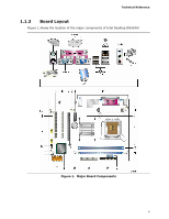
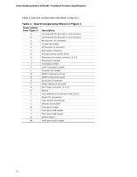
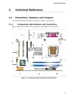
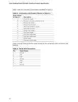
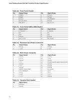
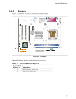
Intel Desktop Board DG41WV Technical Product Specification Table 3 lists the connectors and headers identified in Figure 2. Table 3. Connectors and Headers Shown in Figure 2 Item/callout in Figure 2 Description A Chassis fan header B Processor core power connector (2 X 2) C Processor fan header D Serial port B connector E Main power connector (2 X 12) F Serial ATA connectors G Intruder alert header H Front panel header I Front panel USB header J Front panel USB header K S/PDIF header L Front panel audio header Table 4 though Table 14 list the signal names for the component-side connectors and headers. Table 4. Serial ATA Connectors Pin Signal Name 1 Ground 2 TXP 3 TXN 4 Ground 5 RXN 6 RXP 7 Ground 14
-
 1
1 -
2
-
3
-
4
-
5
-
6
-
7
-
8
-
 9
9 -
 10
10 -
 11
11 -
 12
12 -
 13
13 -
 14
14 -
 15
15 -
 16
16 -
 17
17 -
 18
18 -
 19
19 -
20
-
21
-
22
-
23
-
24
-
25
-
26
-
27
-
28
-
29
-
30
-
31
-
32
-
33
-
34
 |
 |
Intel Desktop Board DG41WV Technical Product Specification
14
Table 3 lists the connectors and headers identified in Figure 2.
Table 3.
Connectors and Headers Shown in Figure 2
Item/callout
in Figure 2
Description
A
Chassis fan header
B
Processor core power connector (2 X 2)
C
Processor fan header
D
Serial port B connector
E
Main power connector (2 X 12)
F
Serial ATA connectors
G
Intruder alert header
H
Front panel header
I
Front panel USB header
J
Front panel USB header
K
S/PDIF header
L
Front panel audio header
Table 4 though Table 14 list the signal names for the component-side connectors and
headers.
Table 4.
Serial ATA Connectors
Pin
Signal Name
1
Ground
2
TXP
3
TXN
4
Ground
5
RXN
6
RXP
7
Ground