Intel BLKDG41WV Product Specification - Page 6

Tables - main

Page 6 highlights

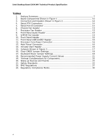
Intel Desktop Board DG41WV Technical Product Specification Tables 1. Feature Summary 7 2. Board Components Shown in Figure 1 10 3. Connectors and Headers Shown in Figure 2 14 4. Serial ATA Connectors 14 5. Serial Port B Connector 15 6. Chassis Fan Header 15 7. Processor Fan Header 15 8. Front Panel Audio Header 15 9. S/PDIF Out Header 15 10. Front Panel Header 16 11. Front Panel USB1/USB2 Header 16 12. Processor Core Power Connector 16 13. Main Power Connector 16 14. Intruder Alert Header 16 15. Jumpers Shown in Figure 3 17 16. Clear CMOS Jumper Settings 18 17. Keyboard Power Jumper Settings 18 18. Recommended Power Supply Current Values 21 19. Thermal Considerations for Components 22 20. Wake-up Devices and Events 22 21. Safety Standards 23 22. EMC Regulations 27 23. Regulatory Compliance Marks 30 vi

  • 1
  • 2
  • 3
  • 4
  • 5
  • 6
  • 7
  • 8
  • 9
  • 10
  • 11
  • 12
  • 13
  • 14
  • 15
  • 16
  • 17
  • 18
  • 19
  • 20
  • 21
  • 22
  • 23
  • 24
  • 25
  • 26
  • 27
  • 28
  • 29
  • 30
  • 31
  • 32
  • 33
  • 34

Intel Desktop Board DG41WV Technical Product Specification
vi
Tables
1.
Feature Summary
..............................................................................
7
2.
Board Components Shown in Figure 1
................................................
10
3.
Connectors and Headers Shown in Figure 2
.........................................
14
4.
Serial ATA Connectors
......................................................................
14
5.
Serial Port B Connector
....................................................................
15
6.
Chassis Fan Header
.........................................................................
15
7.
Processor Fan Header
......................................................................
15
8.
Front Panel Audio Header
.................................................................
15
9.
S/PDIF Out Header
..........................................................................
15
10. Front Panel Header
..........................................................................
16
11. Front Panel USB1/USB2 Header
.........................................................
16
12. Processor Core Power Connector
........................................................
16
13. Main Power Connector
......................................................................
16
14. Intruder Alert Header
.......................................................................
16
15. Jumpers Shown in Figure 3
...............................................................
17
16. Clear CMOS Jumper Settings
.............................................................
18
17. Keyboard Power Jumper Settings
.......................................................
18
18. Recommended Power Supply Current Values
.......................................
21
19. Thermal Considerations for Components
.............................................
22
20. Wake-up Devices and Events
............................................................
22
21. Safety Standards
.............................................................................
23
22. EMC Regulations
.............................................................................
27
23. Regulatory Compliance Marks
............................................................
30