Intel BOXD955XBKLKR Product Specification - Page 21
Intel, 955X Chipset
 |
UPC - 735858173803
View all Intel BOXD955XBKLKR manuals
Add to My Manuals
Save this manual to your list of manuals |
Page 21 highlights
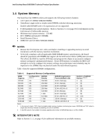
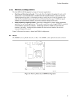
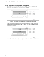
Product Description 1.5 Intel® 955X Chipset The Intel 955X chipset consists of the following devices: • Intel 82955X Memory Controller Hub (MCH) with Direct Media Interface (DMI) interconnect • Intel 82801GR I/O Controller Hub (ICH7-R) with DMI interconnect • BIOS storage in one of the following: ⎯ Firmware Hub (FWH) ⎯ Serial Peripheral Interface (SPI) Flash device The MCH is a centralized controller for the system bus, the memory bus, the PCI Express bus, and the DMI interconnect. The ICH7-R is a centralized controller for the board's I/O paths. For information about The Intel 955X chipset Resources used by the chipset Refer to http://developer.intel.com/ Chapter 2 1.5.1 USB The board supports up to eight USB 2.0 ports, supports UHCI and EHCI, and uses UHCI- and EHCI-compatible drivers. The ICH7-R provides the USB controller for all ports. The port arrangement is as follows: • Four ports are implemented with dual stacked back panel connectors adjacent to the audio connectors • Four ports are routed to two separate front panel USB connectors NOTES Computer systems that have an unshielded cable attached to a USB port may not meet FCC Class B requirements, even if no device is attached to the cable. Use shielded cable that meets the requirements for full-speed devices. For information about The location of the USB connectors on the back panel The location of the front panel USB connectors Refer to Figure 18, page 55 Figure 19, page 56 1.5.2 IDE Support The board provides five IDE interface connectors: • One parallel ATA IDE connector that supports two devices • Four serial ATA IDE connectors that support one device per connector 1.5.2.1 Parallel ATE IDE Interface The ICH7-R's Parallel ATA IDE controller has one bus-mastering Parallel ATA IDE interface. The Parallel ATA IDE interface supports the following modes: • Programmed I/O (PIO): processor controls data transfer. • 8237-style DMA: DMA offloads the processor, supporting transfer rates of up to 16 MB/sec. 21
-
 1
1 -
2
-
3
-
4
-
5
-
6
-
7
-
8
-
9
-
10
-
11
-
12
-
13
-
14
-
15
-
 16
16 -
 17
17 -
 18
18 -
 19
19 -
 20
20 -
 21
21 -
 22
22 -
 23
23 -
 24
24 -
 25
25 -
 26
26 -
27
-
28
-
29
-
30
-
31
-
32
-
33
-
34
-
35
-
36
-
37
-
38
-
39
-
40
-
41
-
42
-
43
-
44
-
45
-
46
-
47
-
48
-
49
-
50
-
51
-
52
-
53
-
54
-
55
-
56
-
57
-
58
-
59
-
60
-
61
-
62
-
63
-
64
-
65
-
66
-
67
-
68
-
69
-
70
-
71
-
72
-
73
-
74
-
75
-
76
-
77
-
78
-
79
-
80
-
81
-
82
-
83
-
84
-
85
-
86
-
87
-
88
-
89
-
90
-
91
-
92
-
93
-
94
 |
 |
