Intel D845GBV Technical Product Specification for Intel Desktop Boards using t - Page 37
Power Connector, 13.2.2, Fan Connectors
 |
View all Intel D845GBV manuals
Add to My Manuals
Save this manual to your list of manuals |
Page 37 highlights
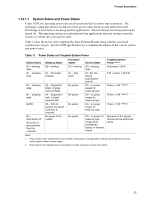
Product Description LAN wake capabilities and Instantly Available PC technology require power from the +5 V standby line. The sections discussing these features describe the incremental standby power requirements for each. Resume on Ring enables telephony devices to access the computer when it is in a power-managed state. The method used depends on the type of telephony device (external or internal). ✏ NOTE The use of Resume on Ring and Wake from USB technologies from an ACPI state requires an operating system that provides full ACPI support. 1.13.2.1 Power Connector ATX12V- and SFX12V-compliant power supplies can turn off the system power through software control. When an ACPI-enabled system receives the correct command, the power supply removes all non-standby voltages. When resuming from an AC power failure, the computer returns to the power state it was in before power was interrupted (on or off). The computer's response can be set using the Last Power State feature in the BIOS Setup program's Boot menu. For information about The ATX specification Refer to Section 1.4, page 13 1.13.2.2 Fan Connectors Table 13 summarizes the function/operation of the fan connectors for boards with a hardware monitoring ASIC18. Table 13. Fan Connector Function/Operation for Desktop Boards with a Hardware Monitoring ASIC Connector Description Processor fan • +12 V DC connection for a processor fan or active fan heatsink. • Fan is on in the S0 or S1 state. Fan is off when the system is off or in the S3, S4, or S5 state. • Wired to a fan tachometer input of the I/O controller. Front chassis fan • +12 V DC connection for a system or chassis fan. • Fan is on in the S0 or S1 state. Fan is off when the system is off or in the S3, S4, or S5 state. Rear chassis fan • +12 V DC connection for a system or chassis fan. • Fan is on in the S0 or S1 state. Fan is off when the system is off or in the S3, S4, or S5 state. • Wired to a fan tachometer input of the I/O controller. 18 Contact your Intel sales representative to determine which type of hardware monitoring ASIC is present on your Intel Desktop Board. 37
-
 1
1 -
2
-
3
-
4
-
5
-
6
-
7
-
8
-
9
-
10
-
11
-
12
-
13
-
14
-
15
-
16
-
17
-
18
-
19
-
20
-
21
-
22
-
23
-
24
-
25
-
26
-
27
-
28
-
29
-
30
-
31
-
 32
32 -
 33
33 -
 34
34 -
 35
35 -
 36
36 -
 37
37 -
 38
38 -
 39
39 -
 40
40 -
 41
41 -
 42
42 -
43
-
44
-
45
-
46
-
47
-
48
-
49
-
50
-
51
-
52
-
53
-
54
-
55
-
56
-
57
-
58
-
59
-
60
-
61
-
62
-
63
-
64
-
65
-
66
-
67
-
68
-
69
-
70
-
71
-
72
-
73
-
74
-
75
-
76
-
77
-
78
-
79
-
80
-
81
-
82
-
83
-
84
-
85
-
86
-
87
-
88
-
89
-
90
 |
 |