Intel D845PEBT2 Product Specification - Page 32
Audio Connectors, Audio Subsystem Software - desktop board drivers
 |
View all Intel D845PEBT2 manuals
Add to My Manuals
Save this manual to your list of manuals |
Page 32 highlights
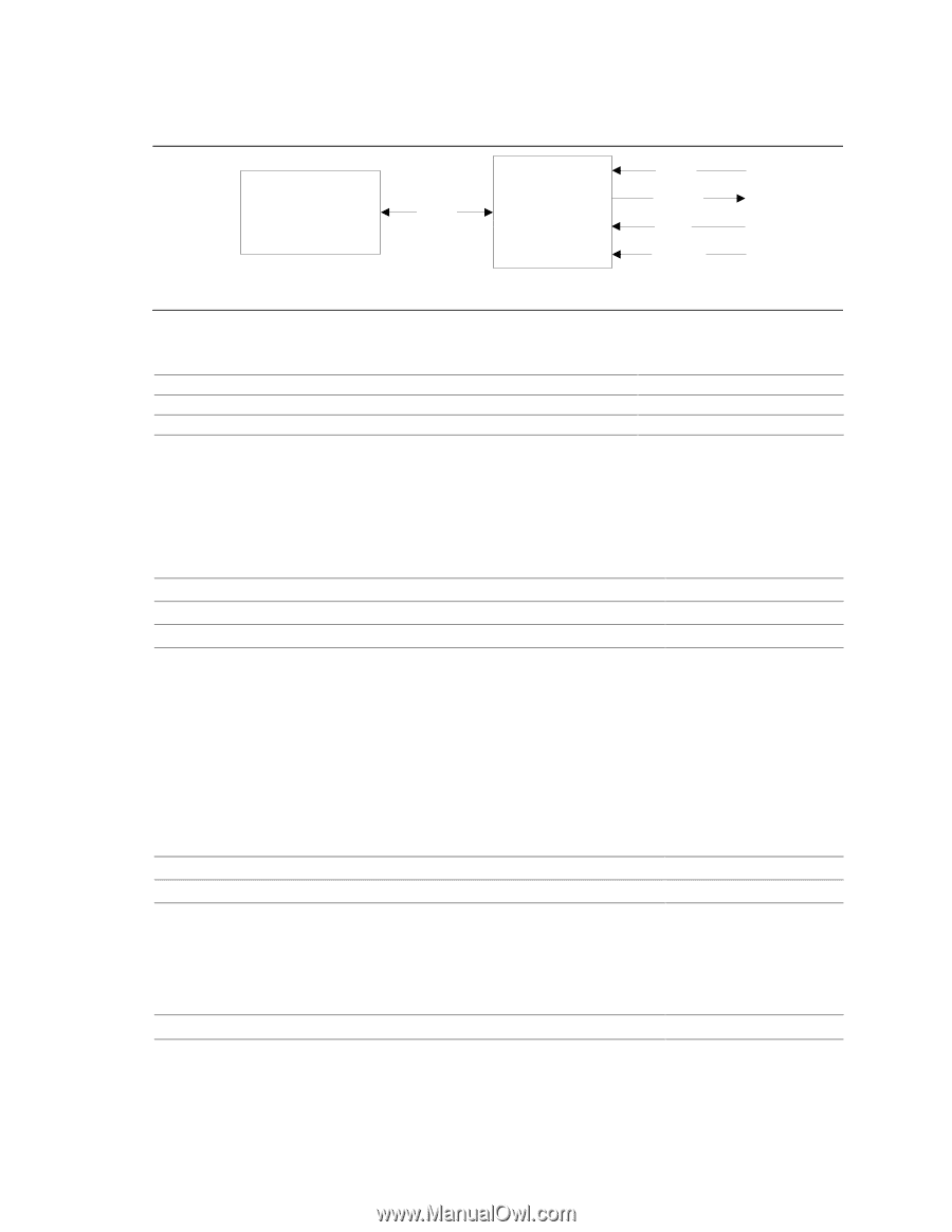
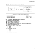
Intel Desktop Board D845PEBT2 Technical Product Specification Figure 6 is a block diagram of the 2-channel audio subsystem. 82801DB I/O Controller Hub (ICH4) AC '97 Link AD1981B Audio Codec Line In Line Out Mic In CD-ROM OM15031 Figure 6. 2-Channel Audio Subsystem Block Diagram For information about Upgrading the onboard audio subsystem using a CNR audio card The front panel audio connector The back panel audio connectors Refer to Section 1.14, page 35 Section 2.8.3, page 68 Section 2.8.1, page 52 1.12.3 Audio Connectors 1.12.3.1 Front Panel Audio Connector A 2 x 5-pin connector provides mic in and line out signals for front panel audio connectors. For information about Refer to The location of the connector Section 2.8.3, page 68 The signal names of the front panel audio connector Table 45, page 69 Obtaining the Front Panel I/O Connectivity Design Guide Section 1.4, page 17 ✏ NOTE The front panel audio connector is alternately used as a jumper block for routing audio signals. Refer to Section 2.9.1 on page 72 for more information. 1.12.3.2 ATAPI-Style CD-ROM Connector A 1 x 4-pin connector connects an internal ATAPI CD-ROM drive to the audio mixer. For information about The location of the ATAPI-style CD-ROM connector The signal names of the ATAPI-style CD-ROM connector Refer to Figure 14, page 61 Table 39, page 65 1.12.4 Audio Subsystem Software Audio software and drivers are available from Intel's World Wide Web site. For information about Obtaining audio software and drivers Refer to Section 1.2, page 16 32
-
 1
1 -
2
-
3
-
4
-
5
-
6
-
7
-
8
-
9
-
10
-
11
-
12
-
13
-
14
-
15
-
16
-
17
-
18
-
19
-
20
-
21
-
22
-
23
-
24
-
25
-
26
-
 27
27 -
 28
28 -
 29
29 -
 30
30 -
 31
31 -
 32
32 -
 33
33 -
 34
34 -
 35
35 -
 36
36 -
 37
37 -
38
-
39
-
40
-
41
-
42
-
43
-
44
-
45
-
46
-
47
-
48
-
49
-
50
-
51
-
52
-
53
-
54
-
55
-
56
-
57
-
58
-
59
-
60
-
61
-
62
-
63
-
64
-
65
-
66
-
67
-
68
-
69
-
70
-
71
-
72
-
73
-
74
-
75
-
76
-
77
-
78
-
79
-
80
-
81
-
82
-
83
-
84
-
85
-
86
-
87
-
88
-
89
-
90
-
91
-
92
-
93
-
94
-
95
-
96
-
97
-
98
-
99
-
100
-
101
-
102
-
103
-
104
-
105
-
106
-
107
-
108
-
109
-
110
-
111
-
112
-
113
-
114
-
115
-
116
-
117
-
118
-
119
-
120
-
121
-
122
-
123
-
124
-
125
-
126
-
127
-
128
 |
 |