Intel D845WN Product Guide
Intel D845WN - P4 PGA478 ATX Motherboard Manual
 |
UPC - 735858149198
View all Intel D845WN manuals
Add to My Manuals
Save this manual to your list of manuals |
Intel D845WN manual content summary:
- Intel D845WN | Product Guide - Page 1
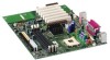
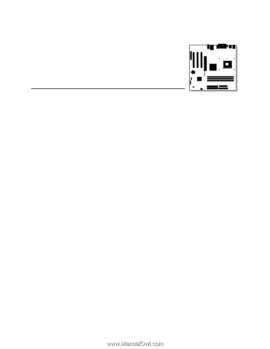
Intel® Desktop Boards D845HV and D845WN Product Guide Order Number: A61038-001 - Intel D845WN | Product Guide - Page 2
Intel® Desktop Boards D845HV and D845WN Product Guide. Date July 2001 If an FCC declaration of conformity marking is present on the board with the instructions, may Intel may make changes to specifications and product descriptions at any time, without notice. The D845HV and D845WN desktop boards - Intel D845WN | Product Guide - Page 3
Contents 1 Desktop Board Features Components...9 Processor ...11 Main Memory ...11 Intel® 845 Chipset ...12 Intel® 82845 Memory Controller Hub (MCH 12 Intel® 82801BA I/O Controller Hub (ICH2 13 Firmware Hub (FWH 13 Input/Output (I/O) Controller 13 Real-Time Clock...13 USB Support ...14 PCI - Intel D845WN | Product Guide - Page 4
Cable 36 Setting the BIOS Configuration Jumper Block 37 Clearing Passwords ...38 Replacing the Battery ...39 3 Updating the BIOS Updating the BIOS with the Intel® Express BIOS Update Utility 43 Updating the BIOS with the Intel® Flash Memory Update Utility 44 Obtaining the BIOS Update File 44 - Intel D845WN | Product Guide - Page 5
5 Technical Reference Board Connectors ...67 Back Panel Connectors 68 Midboard Connectors 69 Front Panel Connectors 73 Desktop Board Resources 74 Memory Map ...74 DMA Channels ...74 I/O Map ...75 Interrupts ...77 A Error Messages and Indicators BIOS Beep Codes ...79 BIOS Error Messages ...80 - Intel D845WN | Product Guide - Page 6
Guide 21. Power and Hardware Control Connectors 70 22. D845HV Board Add-in Card and Peripheral Interface Connectors 71 23. D845WN Board Add-in Card and Peripheral Interface Connectors 72 24. Front Panel Connectors 73 Tables 1. Feature Summary ...7 2. Processors Supported by the Desktop Board - Intel D845WN | Product Guide - Page 7
Audio • microATX at 9.6 inches by 9.6 inches (D845HV board) • ATX at 12 inches by 9.6 inches (D845WN board) • Support for an Intel® Pentium® 4 processor in an mPGA-478 socket • Three SDRAM DIMM sockets. • Designed to support up to 3.0 GB of system memory NOTE The D845HV and D845WN desktop boards - Intel D845WN | Product Guide - Page 8
• SCSI hard drive activity LED connector for the front panel • Speaker ✏ NOTE For information about Intel® desktop boards, including technical product specifications, BIOS updates, and device drivers, go to the Intel World Wide Web site at: http://support.intel.com/support/motherboards/desktop/ 8 - Intel D845WN | Product Guide - Page 9
input) T Front chassis fan connector G Intel 82845 Memory Controller Hub (MCH) U Alternate power/sleep LED connector H Processor socket V Front panel connector I Processor fan connector (tachometer input) W Front panel USB connector J DIMM sockets X BIOS configuration jumper K Serial port - Intel D845WN | Product Guide - Page 10
input) T Front chassis fan connector G Intel 82845 Memory Controller Hub (MCH) U Alternate power/sleep LED connector H Processor socket V Front panel connector I Processor fan connector (tachometer input) W Front panel USB connector J DIMM sockets X BIOS configuration jumper K Serial port - Intel D845WN | Product Guide - Page 11
at: http://support.intel.com/support/motherboards/desktop/ For instructions on installing or upgrading the processor, see Chapter 2 on page 21. The D845HV and D845WN boards require an ATX12V compliant power supply to function according to desktop board specifications. Both boards have two ATX12V - Intel D845WN | Product Guide - Page 12
Mbit technology) ✏ NOTE The D845HV and D845WN desktop boards have been designed to support DIMMs based on 512 Mbit technology up to 3 GB, but this technology has not been validated on these boards. For more information about the latest list of tested memory, refer to the Intel World Wide Web site at - Intel D845WN | Product Guide - Page 13
Desktop Board Features Intel® 82801BA I/O Controller Hub (ICH2) The Intel 82801BA I/O Controller Hub integrates many I/O functions and provides the I/O subsystem with access to the rest of the platform. ICH2 features on D845HV and D845WN boards includes: • Integrated IDE controller supports two - Intel D845WN | Product Guide - Page 14
the back panel, two to the front panel connector, and one to the optional CNR. To attach additional devices, connect an external hub to either of the built-in ports. The board supports the standard universal host controller interface (UHCI) and takes advantage of standard software drivers written to - Intel D845WN | Product Guide - Page 15
: http://support.intel.com/support/motherboards/desktop/ BIOS The BIOS provides the Power-On Self-Test (POST), the BIOS Setup program, the PCI and IDE auto-configuration utilities, and the video BIOS. The BIOS is stored in the Firmware Hub. The BIOS can be updated by following the instructions in - Intel D845WN | Product Guide - Page 16
connector with status indicator LEDs • Programmable transit threshold • Configurable EEPROM that contains the MAC address LAN Subsystem Software For LAN software and drivers, refer to the D845HV or D845WN link on Intel's World Wide Web site at: http://support.intel.com/support/motherboards/desktop - Intel D845WN | Product Guide - Page 17
on the desktop board. The speaker provides audible error code (beep code) information during the Power-On Self-Test (POST). Battery A battery on the board keeps the values in CMOS RAM and the clock current when the computer is turned off. See Chapter 2 starting on page 21 for instructions on how - Intel D845WN | Product Guide - Page 18
awake state. The board's standby power indicator, shown in Figure 3, is lit when there is standby power to the system. This includes the memory modules and PCI bus connectors, even when the computer appears to be off. If the system has a dual-colored power LED on the front panel, the sleep state - Intel D845WN | Product Guide - Page 19
, the desktop board may lose register settings stored in memory. Power supplies used with this board must be able to provide enough standby current to support the standard Instantly Available (ACPI S3 sleep state) configuration as outlined in Table 4. Values are determined by specifications such as - Intel D845WN | Product Guide - Page 20
Intel Desktop Boards D845HV and D845WN Product Guide ✏ NOTE PCI requirements are calculated by totaling the following: • One wake-enabled device @ 375 mA. • Five non wake-enabled devices @ 20 mA each. PS/2 Ports requirements per the IBM PS/2 Port Specification (Sept 1991): • Keyboard @ 275 mA. • - Intel D845WN | Product Guide - Page 21
the desktop board • Install and remove a processor • Install and remove memory • Install and remove an AGP retention mechanism and card • Connect the IDE cable • Set the BIOS jumper • damage. Some circuitry on the board can continue to operate even though the front panel power button is off. 21 - Intel D845WN | Product Guide - Page 22
Intel Desktop Boards D845HV and D845WN Product Guide Installing the I/O Shield The board comes with an I/O shield. When installed promotes correct airflow within the chassis. Install the I/O shield before installing the board in the chassis. Place the shield inside the chassis as shown in Figure - Intel D845WN | Product Guide - Page 23
Installing and Replacing Desktop Board Components Installing and Removing the Desktop Board Refer to your chassis manual for instructions on installing and removing the board. The D845HV board is secured to the chassis by eight screws and the D845WN board by 11 screws. See Figure 5 and Figure 6 for - Intel D845WN | Product Guide - Page 24
Intel Desktop Boards D845HV and D845WN Product Guide Figure 6 shows the location of the mounting holes for the D850WN board. Figure 6. D845WN Board Mounting Holes OM12080 24 - Intel D845WN | Product Guide - Page 25
) base and processor to the desktop board are given below. For instruction on how to install the processor fan heatsink, refer to the processor installation manual or the Intel World Wide Web site: http://support.intel.com/support/motherboards/desktop Installing the Processor Fan Heatsink Retention - Intel D845WN | Product Guide - Page 26
Intel Desktop Boards D845HV and D845WN Product Guide 3. Align the four fasteners (B) of the processor fan heatsink RM base with the corresponding holes in the desktop board (C). Gently press the base down until all four corners snap into place. Verify that all four fasteners are fully engaged, then - Intel D845WN | Product Guide - Page 27
mPGA478B mPGA478B A Figure 9. Installing a Processor OM12078 Installing the Processor Fan Heatsink For instructions on how to install the processor fan heatsink, refer to the boxed processor manual or the Intel World Wide Web site at: http://support.intel.com/support/motherboards/desktop 27 - Intel D845WN | Product Guide - Page 28
Cable to the Processor Fan Connector Removing a Processor For instruction on how to remove the processor fan heatsink, refer to the processor installation manual or the Intel World Wide Web site at: http://support.intel.com/support/motherboards/desktop ✏ NOTE Once removed, the processor fan heatsink - Intel D845WN | Product Guide - Page 29
Intel® SDRAM memory specifications, the boards require DIMMs that support the Serial Presence Detect (SPD) data structure. You can access the PC Serial Presence Detect Specification at: http://www.intel.com/technology/memory/pcsdram/spec/ The boards have three 168-pin DIMM sockets arranged - Intel D845WN | Product Guide - Page 30
Intel Desktop Boards D845HV and D845WN Product Guide 0 1 2 OM11986 Figure 11. Installing a Memory Module 5. Make sure the clips at either end of the DIMM socket(s) are pushed outward to the open position. 6. Holding the DIMM by the edges, remove it from its anti-static package. 7. Position the DIMM - Intel D845WN | Product Guide - Page 31
Desktop Board Components Removing DIMMs To remove a memory module, follow these steps: 1. Observe the precautions in "Before You Begin" on page 21. 2. Turn off all peripheral devices connected DIMM socket. The DIMM pops out of the socket. 7. Hold the DIMM by the edges, lift it away from the socket, - Intel D845WN | Product Guide - Page 32
Intel Desktop Boards D845HV and D845WN Product Guide Installing and Removing the AGP Retention Mechanism and Card The AGP connector supports 1.5 V to remove the AGP card RM, follow the instructions on page 35. ✏ NOTE All D845HV and D845WN boxed desktop boards may not include an AGP RM. See " - Intel D845WN | Product Guide - Page 33
Installing and Replacing Desktop Board Components The AGP card RM (see Figure 13) encloses the board's AGP connector and stabilizes the AGP card. Place the board (component side up) on a flat, supportive surface, preferably on the anti-static bag in which the board was shipped. Follow the steps - Intel D845WN | Product Guide - Page 34
Intel Desktop Boards D845HV and D845WN Product Guide Installing an AGP Card Follow these instructions to install an AGP card: 1. Place the AGP card in the AGP connector. 2. Press down on the card until it is completely seated in the AGP connector and the card retention notch snaps into place around - Intel D845WN | Product Guide - Page 35
Installing and Replacing Desktop Board Components Removing the AGP Card Retention Mechanism Follow these instructions to remove the AGP card retention mechanism: 1. Using diagonal cutters (A), cut the loop (B) joining the two sides of the retention mechanism (see Figure 15). 2. Spread - Intel D845WN | Product Guide - Page 36
Intel Desktop Boards D845HV and D845WN Product Guide Connecting the IDE Cable The Intel® boxed desktop board package includes two IDE cables. Both are capable of connecting two drives to the desktop board. The 40-contact cable supports the Ultra DMA-33 transfer protocol. The 40-contact, 80-conductor - Intel D845WN | Product Guide - Page 37
Replacing Desktop Board Components Setting the BIOS Configuration Jumper Block CAUTION Always turn off the power and unplug the power cord from the computer before changing the jumper. Moving the jumper with the power on may result in unreliable computer operation. The location of the board's BIOS - Intel D845WN | Product Guide - Page 38
Desktop Boards D845HV and D845WN Product Guide Clearing Passwords This procedure assumes that the board is installed in the computer and the configuration jumper block is set to normal mode. 1. Observe the precautions in "Before You Begin" on page 21. 2. Turn off all peripheral devices connected - Intel D845WN | Product Guide - Page 39
Desktop Board Components Replacing the Battery A coin-cell battery (CR2032) powers the real-time clock and CMOS memory. When the computer is not plugged into a wall socket voltage drops below a certain level, the BIOS Setup program settings stored in CMOS RAM (for example, the date and time) might - Intel D845WN | Product Guide - Page 40
Intel Desktop Boards D845HV and D845WN Product Guide VORSICHT Bei falschem Einsetzen einer neuen Batterie besteht Explosionsgefahr. Die Batterie darf nur durch denselben oder einen entsprechenden, vom Hersteller empfohlenen Batterietyp ersetzt werden. Entsorgen - Intel D845WN | Product Guide - Page 41
devices connected to the computer. Disconnect the computer's power cord from the ac power source (wall outlet or power adapter). 3. Remove the computer cover. 4. Locate the battery on the board (see Figure 18). 5. With a medium flat-bladed screwdriver, gently pry the battery free from its connector - Intel D845WN | Product Guide - Page 42
Intel Desktop Boards D845HV and D845WN Product Guide 42 - Intel D845WN | Product Guide - Page 43
of the Intel Flash Memory Update Utility and the ease-of use of Windows-based installation wizards. To update the BIOS with the Intel Express BIOS Update utility: 1. Go to the Intel World Wide Web site: http://support.intel.com/support/motherboards/desktop/ 2. Navigate to the D845HV or D845WN - Intel D845WN | Product Guide - Page 44
the D845HV or D845WN page on the Intel World Wide Web site: http://support.intel.com/support/motherboards/desktop ✏ NOTE Please review the instructions distributed with the update utility before attempting a BIOS update. The Intel Flash Memory Update Utility allows you to: • Update the BIOS in flash - Intel D845WN | Product Guide - Page 45
jumper block (J9G1) (see Figure 17). 3. Remove the jumper from all pins as shown below to set recovery mode for Setup. 1 3 4. Insert the bootable BIOS update diskette into diskette drive A. 5. Replace the computer cover, connect BIOS recovery. • A series of continuous beeps indicates a failed BIOS - Intel D845WN | Product Guide - Page 46
Intel Desktop Boards D845HV and D845WN Product Guide 46 - Intel D845WN | Product Guide - Page 47
in this section may not show the latest settings. For the latest BIOS settings, refer to the Intel Desktop Board D845HV/D845WN Technical Product Specification or the Intel World Wide Web site: http://support.intel.com/support/motherboards/desktop ✏ NOTE For reference purposes, you should write down - Intel D845WN | Product Guide - Page 48
Intel Desktop Boards D845HV and D845WN Product Guide Table 7 shows the function keys available for menu screens. Table 7. BIOS Setup Program Function Keys BIOS Setup Program Function Key or or Description Selects a different menu screen Moves cursor up or - Intel D845WN | Product Guide - Page 49
. Cache lookups are not performed. Both the video driver and the application must support Write Combining. Selects UnCacheable (UC) video memory cache mode. This setting identifies the video memory range as uncacheable by the processor. Memory writes are performed in program order. Cache lookups are - Intel D845WN | Product Guide - Page 50
Intel Desktop Boards D845HV and D845WN Product Guide Main Menu Maintenance Main Advanced Security Power Boot Exit Table 10 describes the Main Menu. This menu reports processor and memory information and is used to configure the system date and system time. Table 10. Main Menu Feature BIOS - Intel D845WN | Product Guide - Page 51
Table 11 describes the Advanced Menu. This menu is used to set advanced features that are available through the chipset. Table 11. When selected, displays the Peripheral Configuration submenu. Specifies type of connected IDE device. When selected, displays the Diskette Configuration submenu. - Intel D845WN | Product Guide - Page 52
Intel Desktop Boards D845HV and D845WN Product Guide PCI Configuration Submenu Maintenance Main Advanced Security Power PCI Configuration Boot Configuration Peripheral Configuration IDE Configuration Diskette Configuration Event Log Configuration Video Configuration Boot Exit - Intel D845WN | Product Guide - Page 53
On (default) Description Specifies if manual configuration is desired. No lets the BIOS configure all devices. This setting is appropriate when using a Plug configuration data stored in flash memory on the next boot. Yes clears the PCI/PnP configuration data stored in flash memory on the next boot. - Intel D845WN | Product Guide - Page 54
Intel Desktop Boards D845HV and D845WN Product Guide Peripheral Configuration Submenu Maintenance Auto (default) • 2F8 (default) • 3E8 • 2E8 Configures serial port B. Auto assigns the first free COM port, normally COM2, the address 2F8h, and the interrupt IRQ3. An * (asterisk) displayed next - Intel D845WN | Product Guide - Page 55
to Enabled) DMA Channel (This feature is present only when Parallel Port Mode is set to ECP) Audio Device LAN Device (This feature is present only when there is onboard LAN) Legacy USB Support Options • Disabled • Enabled • Auto (default) • Output Only • Bi-directional (default) • EPP • ECP • 378 - Intel D845WN | Product Guide - Page 56
Intel Desktop Boards D845HV and D845WN Product Guide IDE Configuration Submenu Maintenance • 15 Seconds • 21 Seconds • 30 Seconds Primary IDE Master No options Reports type of connected IDE device. When selected, displays the Primary IDE Master submenu. Primary IDE Slave No options Reports - Intel D845WN | Product Guide - Page 57
or disables LBA mode control. Specifies number of sectors per block for transfers from the hard disk drive to memory. Check the hard disk drive's specifications for optimum setting. Specifies the PIO mode. Note: These configuration options appear only if an IDE device is installed. continued 57 - Intel D845WN | Product Guide - Page 58
Intel Desktop Boards D845HV and D845WN Product Guide Table 16. Primary/Secondary IDE Master/Slave Submenus (continued) Feature Ultra DMA Cable Detected (Note) Options • Disabled (default) • Mode 0 • Mode 1 • Mode 2 • Mode 3 • Mode 4 None Description - Intel D845WN | Product Guide - Page 59
Using the Setup Program Event Log Configuration Submenu Maintenance Main Advanced Security Power PCI Configuration Boot Configuration Peripheral Configuration IDE Configuration Diskette Configuration Event Log Configuration Video Configuration Boot The submenu shown in Table 18 is used to - Intel D845WN | Product Guide - Page 60
Intel Desktop Boards D845HV and D845WN Product Guide Video Configuration Submenu Maintenance Main Advanced that the onboard graphics subsystem is enabled on the D845HV and D845WN boards only. 2x AGP Card or 4x AGP Card indicates that the BIOS has detected a 2x or 4x AGP card. Installing - Intel D845WN | Product Guide - Page 61
(default) Clears the user password. • No • Limited • No Access Sets BIOS Setup Utility access rights for user level. • View Only • Full (default has been set. 2. This feature appears only if both a user password and a supervisor password have been set. 3. If both Legacy USB Support (in the - Intel D845WN | Product Guide - Page 62
Intel Desktop Boards D845HV and D845WN Product Guide Power Menu Maintenance Main Advanced Security Power The menu shown in Table 21 is used to set sleep state. • S3 State (default) • Disabled (default) Allows the video BIOS to be initialized coming out of the • Enabled S3 state. Some video - Intel D845WN | Product Guide - Page 63
used to set the boot features and the boot sequence. Exit Table 23. Boot Menu Feature Quiet Boot Intel® Rapid BIOS Boot Scan User Flash Area Boot computer to boot without running certain POST tests. Enables the BIOS to scan the flash memory for user binary files that are executed at boot time. - Intel D845WN | Product Guide - Page 64
Intel Desktop Boards D845HV and D845WN Product Guide Boot Device Priority Submenu Maintenance Main Advanced Security Power Boot Exit Boot Device Priority Hard Disk Drives Removable Devices ATAPI CD-ROM Drives The submenu represented in Table 24 is for setting boot devices priority. - Intel D845WN | Product Guide - Page 65
up to twelve hard disk drives, the maximum number of hard disk drives supported by the BIOS. Removable Devices Submenu Maintenance Main Advanced Security Power The submenu in shown Table 26 is for setting removable devices. Boot Exit Boot Device Priority Hard Disk Drives Removable Devices - Intel D845WN | Product Guide - Page 66
Intel Desktop Boards D845HV and D845WN Product Guide ATAPI CD-ROM Drives Maintenance Main Advanced Security Power Boot Exit Boot Device Priority Hard Disk Drives Removable Devices ATAPI CD-ROM Drives The submenu shown in Table 27 is for setting ATAPI CD-ROM drives. Table 27. ATAPI CD- - Intel D845WN | Product Guide - Page 67
Board Connectors The board connectors can be divided into three groups: • Back panel connectors • Midboard connectors Audio connectors Power and hardware connectors Add-in board and peripheral interface connectors • Front panel connectors CAUTION Many of the midboard and front panel connectors - Intel D845WN | Product Guide - Page 68
Intel Desktop Boards D845HV and D845WN Product Guide Back Panel Connectors Figure 19 shows the back panel connectors on the board. A E G C BD F Item A B C D E F G H I J K L Description PS/2 mouse port PS/2 keyboard port USB port 0 USB port 1 Parallel port Serial port A RJ-45 (optional) USB - Intel D845WN | Product Guide - Page 69
Midboard Connectors Audio Connectors Figure 20 shows the location of the audio connectors. A BC 4 1 4 1 1 2 9 10 Technical Reference Item A B C Description Color Front panel audio CD-ROM (ATAPI) Auxiliary line in (ATAPI) Black Black White Figure 20. Audio Connectors OM11991 69 - Intel D845WN | Product Guide - Page 70
desktop board. The D845HV and D845WN boards require an ATX12V compliant power supply to function according to desktop board specifications. Both boards have two ATX12V compliant power supply connectors that are needed to provide extra power to the Intel 845 chipset and Pentium 4 processor. Figure - Intel D845WN | Product Guide - Page 71
shows the add-in card and peripheral interface connectors for the D845HV board. A B C DE 40 2 1 39 40 2 2 34 1 1 33 39 Item A B C D H Description CNR (optional) PCI bus connector 3 PCI bus connector 2 PCI bus connector 1 G F Item E F G H Description AGP Diskette drive Primary IDE - Intel D845WN | Product Guide - Page 72
Intel Desktop Boards D845HV and D845WN Product Guide Figure 23 shows the add-in card and peripheral interface connectors for the D845WN board. A B C D E F GH 40 2 1 39 40 2 2 34 1 1 33 39 Item A B C D E F Description CNR (optional) PCI bus connector 6 PCI bus connector 5 PCI bus - Intel D845WN | Product Guide - Page 73
Front Panel Connectors Figure 24 shows the location of the front panel connectors. Technical Reference 12 9 10 7 10 2 1 1 16 15 2 1 AB C D Item A B C D Description Front panel Alternate power/sleep LED Front panel USB Front panel audio OM11994 Figure 24. Front Panel Connectors 73 - Intel D845WN | Product Guide - Page 74
Intel Desktop Boards D845HV and D845WN Product Guide Desktop Board Resources Memory Map Table 29. System Memory Map Address Range (decimal) 1024 K - 3145728 K 960 K - 1024 K 896 K - 960 K 800 K - 896 K Address Range (hex) 100000 - 1BFFFFFFF F0000 - FFFFF E0000 - EFFFF C8000 - DFFFF 640 K - 800 - Intel D845WN | Product Guide - Page 75
controller, CMD / STAT byte System CMOS / Real Time Clock System CMOS DMA controller Fast A20 and PIC PIC APM control DMA Numeric data processor Secondary IDE channel Primary IDE channel LPT3 LPT2 COM4 / video (8514A) COM2 Secondary IDE channel command port Secondary IDE channel status port LPT1 - Intel D845WN | Product Guide - Page 76
Intel Desktop Boards D845HV and D845WN Product Guide Table 31. I/O Map (continued) Address (hex) 96 contiguous TCO) D845HV and D845WN board resources ICH2 (USB controller #1) ICH2 (SMBus) Intel 82801BA PCI bridge ICH2 audio mixer ICH2 audio bus mixer ICH2 (USB controller #2) ICH2/Intel 82562ET ( - Intel D845WN | Product Guide - Page 77
Interrupts Table 32. Interrupts IRQ System Resource NMI I/O channel check 0 Reserved, interval timer 1 Reserved, keyboard buffer full 2 Reserved, cascade interrupt from slave PIC 3 COM2* 4 COM1* 5 LPT2 (Plug and Play option) / ** 6 Diskette drive controller 7 LPT1* 8 Real time - Intel D845WN | Product Guide - Page 78
Intel Desktop Boards D845HV and D845WN Product Guide 78 - Intel D845WN | Product Guide - Page 79
A Error Messages and Indicators The D845HV and D845WN boards report POST errors in two ways: • By sounding a beep code • By displaying an error message on the monitor BIOS Beep Codes The BIOS beep codes are listed in Table 33. The BIOS also issues a beep code (one long tone followed by two short - Intel D845WN | Product Guide - Page 80
Intel Desktop Boards D845HV and D845WN Product Guide BIOS Error Messages When a recoverable error occurs during the POST, the BIOS displays an error message describing the problem. Table 34. BIOS Error Messages Error Message Explanation GA20 Error An error occurred with Gate-A20 when switching - Intel D845WN | Product Guide - Page 81
On Board Parity Error Parity Error NVRAM / CMOS / PASSWORD cleared by Jumper Pressed Explanation Memory size has decreased since the last boot. If no memory was removed, then memory may be bad. Memory size has increased since the last boot. If no memory was added, there may be a problem - Intel D845WN | Product Guide - Page 82
Intel Desktop Boards D845HV and D845WN Product Guide 82 - Intel D845WN | Product Guide - Page 83
D845HV and D845WN desktop boards. • Instructions and precautions for integrators who are installing this desktop board in a chassis. Safety Regulations This desktop board , (Class B) CISPR 24: 1997 Title Title 47 of the Code of Federal Regulations, Parts 2 and 15, Subpart B, Radiofrequency Devices - Intel D845WN | Product Guide - Page 84
Intel Desktop Boards D845HV and D845WN Product Guide Product Certification Markings The desktop boards Intel desktop boards: E210882 (component side). • FCC Declaration of Conformity logo mark for Class B equipment; includes Intel Intel supplier code number, N-232. • Printed wiring board manufacturer - Intel D845WN | Product Guide - Page 85
and test the desktop board, observe all warnings and cautions in the installation instructions. To avoid injury, be careful of: • Sharp pins on connectors • Sharp pins on printed circuit assemblies • Rough edges and sharp corners on the chassis • Hot components (like processors, voltage regulators - Intel D845WN | Product Guide - Page 86
Intel Desktop Boards D845HV and D845WN Product Guide Ensure Electromagnetic Compatibility (EMC) Compliance Before computer integration, make sure that the power supply and other modules or peripherals, as applicable, have passed Class B EMC - Intel D845WN | Product Guide - Page 87
equivalent type recommended by the manufacturer. Dispose of used batteries according to the manufacturer's instructions. Use Only for Intended Applications All Intel desktop processor boards are evaluated as Information Technology Equipment (I.T.E.) for use in personal computers for installation in
-
 1
1 -
 2
2 -
 3
3 -
 4
4 -
 5
5 -
 6
6 -
 7
7 -
8
-
9
-
10
-
11
-
12
-
13
-
14
-
15
-
16
-
17
-
18
-
19
-
20
-
21
-
22
-
23
-
24
-
25
-
26
-
27
-
28
-
29
-
30
-
31
-
32
-
33
-
34
-
35
-
36
-
37
-
38
-
39
-
40
-
41
-
42
-
43
-
44
-
45
-
46
-
47
-
48
-
49
-
50
-
51
-
52
-
53
-
54
-
55
-
56
-
57
-
58
-
59
-
60
-
61
-
62
-
63
-
64
-
65
-
66
-
67
-
68
-
69
-
70
-
71
-
72
-
73
-
74
-
75
-
76
-
77
-
78
-
79
-
80
-
81
-
82
-
83
-
84
-
85
-
86
-
87
 |
 |
Intel
®
Desktop Boards
D845HV and D845WN
Product Guide
Order Number:
A61038-001