Intel D845WN Product Guide - Page 23
Installing and Removing the Desktop Board, WARNING, NOTES - desktop board manual
 |
UPC - 735858149198
View all Intel D845WN manuals
Add to My Manuals
Save this manual to your list of manuals |
Page 23 highlights
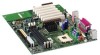
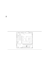
Installing and Replacing Desktop Board Components Installing and Removing the Desktop Board Refer to your chassis manual for instructions on installing and removing the board. The D845HV board is secured to the chassis by eight screws and the D845WN board by 11 screws. See Figure 5 and Figure 6 for the locations of the mounting holes of each board. WARNING This procedure should be done only by qualified technical personnel. Disconnect the computer from its power source before performing the procedures described here. Failure to disconnect the power before you open the computer can result in personal injury or equipment damage. ✏ NOTES You will need a Phillips† (#2 bit) screwdriver. Refer to Appendix B for regulatory requirements and installation instructions and precautions. Figure 5 shows the location of the mounting holes for the D845HV board. OM11982 Figure 5. D845HV Board Mounting Holes 23
-
 1
1 -
2
-
3
-
4
-
5
-
6
-
7
-
8
-
9
-
10
-
11
-
12
-
13
-
14
-
15
-
16
-
17
-
 18
18 -
 19
19 -
 20
20 -
 21
21 -
 22
22 -
 23
23 -
 24
24 -
 25
25 -
 26
26 -
 27
27 -
 28
28 -
29
-
30
-
31
-
32
-
33
-
34
-
35
-
36
-
37
-
38
-
39
-
40
-
41
-
42
-
43
-
44
-
45
-
46
-
47
-
48
-
49
-
50
-
51
-
52
-
53
-
54
-
55
-
56
-
57
-
58
-
59
-
60
-
61
-
62
-
63
-
64
-
65
-
66
-
67
-
68
-
69
-
70
-
71
-
72
-
73
-
74
-
75
-
76
-
77
-
78
-
79
-
80
-
81
-
82
-
83
-
84
-
85
-
86
-
87
 |
 |
