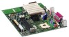
Intel D845WN Product Guide - Page 17
RJ-45 LAN Connector LEDs, Speaker, Battery, Power Management Features - beep codes
 |
UPC - 735858149198
View all Intel D845WN manuals
Add to My Manuals
Save this manual to your list of manuals |
Page 17 highlights
Desktop Board Features RJ-45 LAN Connector LEDs Two LEDs are built into the RJ-45 LAN connector. Table 3 describes the LED states when the board is powered up and the LAN subsystem is operating. Table 3. RJ-45 LAN Connector LEDs LED Color LED State Indicates Green Off 10 Mbit/sec data rate is selected. On 100 Mbit/sec data rate is selected. Yellow Off LAN link is not established. On (steady state) LAN link is established. On (brighter and pulsing) The computer is communicating with another computer on the LAN. Speaker A 47 Ω inductive speaker is mounted on the desktop board. The speaker provides audible error code (beep code) information during the Power-On Self-Test (POST). Battery A battery on the board keeps the values in CMOS RAM and the clock current when the computer is turned off. See Chapter 2 starting on page 21 for instructions on how to replace the battery. Power Management Features Power management is implemented at several levels, including: • Software support: Advanced Configuration and Power Interface (ACPI) Instantly Available PC (IAPC) • Hardware support: Resume on Ring Instantly Available technology Wake from USB Wake from PS/2 keyboard PCI card wake up support 17
-
 1
1 -
2
-
3
-
4
-
5
-
6
-
7
-
8
-
9
-
10
-
11
-
 12
12 -
 13
13 -
 14
14 -
 15
15 -
 16
16 -
 17
17 -
 18
18 -
 19
19 -
 20
20 -
 21
21 -
 22
22 -
23
-
24
-
25
-
26
-
27
-
28
-
29
-
30
-
31
-
32
-
33
-
34
-
35
-
36
-
37
-
38
-
39
-
40
-
41
-
42
-
43
-
44
-
45
-
46
-
47
-
48
-
49
-
50
-
51
-
52
-
53
-
54
-
55
-
56
-
57
-
58
-
59
-
60
-
61
-
62
-
63
-
64
-
65
-
66
-
67
-
68
-
69
-
70
-
71
-
72
-
73
-
74
-
75
-
76
-
77
-
78
-
79
-
80
-
81
-
82
-
83
-
84
-
85
-
86
-
87
 |
 |
