Intel D915PLWD English Product Guide - Page 31
Installing the Processor Fan Heat Sink
 |
View all Intel D915PLWD manuals
Add to My Manuals
Save this manual to your list of manuals |
Page 31 highlights
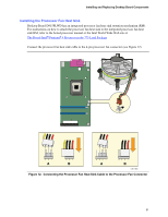
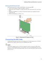
Installing and Replacing Desktop Board Components Installing the Processor Fan Heat Sink Desktop Board D915PLWD has an integrated processor fan heat sink retention mechanism (RM). For instructions on how to attach the processor fan heat sink to the integrated processor fan heat sink RM, refer to the boxed processor manual or the Intel World Wide Web site at: The Boxed Intel® Pentium® 4 Processor in the 775-Land Package Connect the processor fan heat sink cable to the 4-pin processor fan connector (see Figure 12). 3 21 A 3 21 B 43 2 1 A 43 2 1 B OM17855 Figure 12. Connecting the Processor Fan Heat Sink Cable to the Processor Fan Connector 31
-
 1
1 -
2
-
3
-
4
-
5
-
6
-
7
-
8
-
9
-
10
-
11
-
12
-
13
-
14
-
15
-
16
-
17
-
18
-
19
-
20
-
21
-
22
-
23
-
24
-
25
-
 26
26 -
 27
27 -
 28
28 -
 29
29 -
 30
30 -
 31
31 -
 32
32 -
 33
33 -
 34
34 -
 35
35 -
 36
36 -
37
-
38
-
39
-
40
-
41
-
42
-
43
-
44
-
45
-
46
-
47
-
48
-
49
-
50
-
51
-
52
-
53
-
54
-
55
-
56
-
57
-
58
-
59
-
60
-
61
-
62
-
63
-
64
-
65
-
66
-
67
-
68
 |
 |
Installing and Replacing Desktop Board Components
31
Installing the Processor Fan Heat Sink
Desktop Board D915PLWD has an integrated processor fan heat sink retention mechanism (RM).
For instructions on how to attach the processor fan heat sink to the integrated processor fan heat
sink RM, refer to the boxed processor manual or the Intel World Wide Web site at:
The Boxed Intel
®
Pentium
®
4 Processor in the 775-Land Package
Connect the processor fan heat sink cable to the 4-pin processor fan connector (see Figure 12).
OM17855
3
1
2
4
3
1
2
4
A
B
3
1
2
3
1
2
B
A
Figure 12.
Connecting the Processor Fan Heat Sink Cable to the Processor Fan Connector