Intel D925XBC Product Guide - Page 44
Front Panel Audio Header, IEEE 1394 Headers, USB 2.0 Headers, Table 6. - d925xcv no audio
 |
View all Intel D925XBC manuals
Add to My Manuals
Save this manual to your list of manuals |
Page 44 highlights
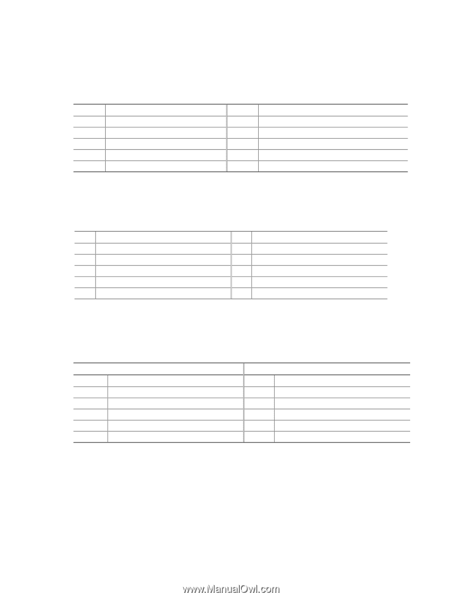
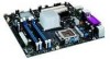
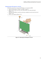
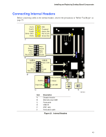
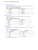
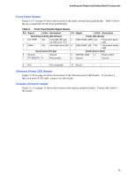
Intel Desktop Board D925XCV/D925XBC Product Guide Front Panel Audio Header Figure 21, F on page 43 shows the location of the yellow front panel audio header. Table 6 shows the pin assignments for the front panel audio header. Table 6. Front Panel Audio Header Signal Names Pin Signal Name 1 Port1L 3 Port1R 5 Port2R 7 Sense Send 9 Port2L Pin Signal Name 2 GND 4 Presence# 6 Sense1 Ret 8 Key (no pin) 10 Sense2 Ret IEEE 1394 Headers See Figure 21, E for the location of the blue IEEE 1394 headers. Table 7 shows the pin assignments for the headers. Table 7. IEEE 1394 Header Signal Names Pin Signal Name 1 TPA1+ 3 Ground 5 TPA2+ 7 +12 V 9 Key (no pin) Pin Signal Name 2 TPA14 Ground 6 TPA28 +12 V 10 Ground USB 2.0 Headers See Figure 21, D for the location of the black USB 2.0 headers. Table 8 shows the pin assignments for the headers. Table 8. USB 2.0 Header Signal Names USB Port A Pin Signal Name 1 Power 3 D- 5 D+ 7 Ground 9 Key Note: USB ports may be assigned as needed. USB Port B Pin Signal Name 2 Power 4 D- 6 D+ 8 Ground 10 No connect 44
-
 1
1 -
2
-
3
-
4
-
5
-
6
-
7
-
8
-
9
-
10
-
11
-
12
-
13
-
14
-
15
-
16
-
17
-
18
-
19
-
20
-
21
-
22
-
23
-
24
-
25
-
26
-
27
-
28
-
29
-
30
-
31
-
32
-
33
-
34
-
35
-
36
-
37
-
38
-
 39
39 -
 40
40 -
 41
41 -
 42
42 -
 43
43 -
 44
44 -
 45
45 -
 46
46 -
 47
47 -
 48
48 -
 49
49 -
50
-
51
-
52
-
53
-
54
-
55
-
56
-
57
-
58
-
59
-
60
-
61
-
62
-
63
-
64
-
65
-
66
-
67
-
68
-
69
-
70
-
71
-
72
 |
 |