Intel D945GCNL Product Specification - Page 51
Front Panel Header
 |
UPC - 735858194570
View all Intel D945GCNL manuals
Add to My Manuals
Save this manual to your list of manuals |
Page 51 highlights
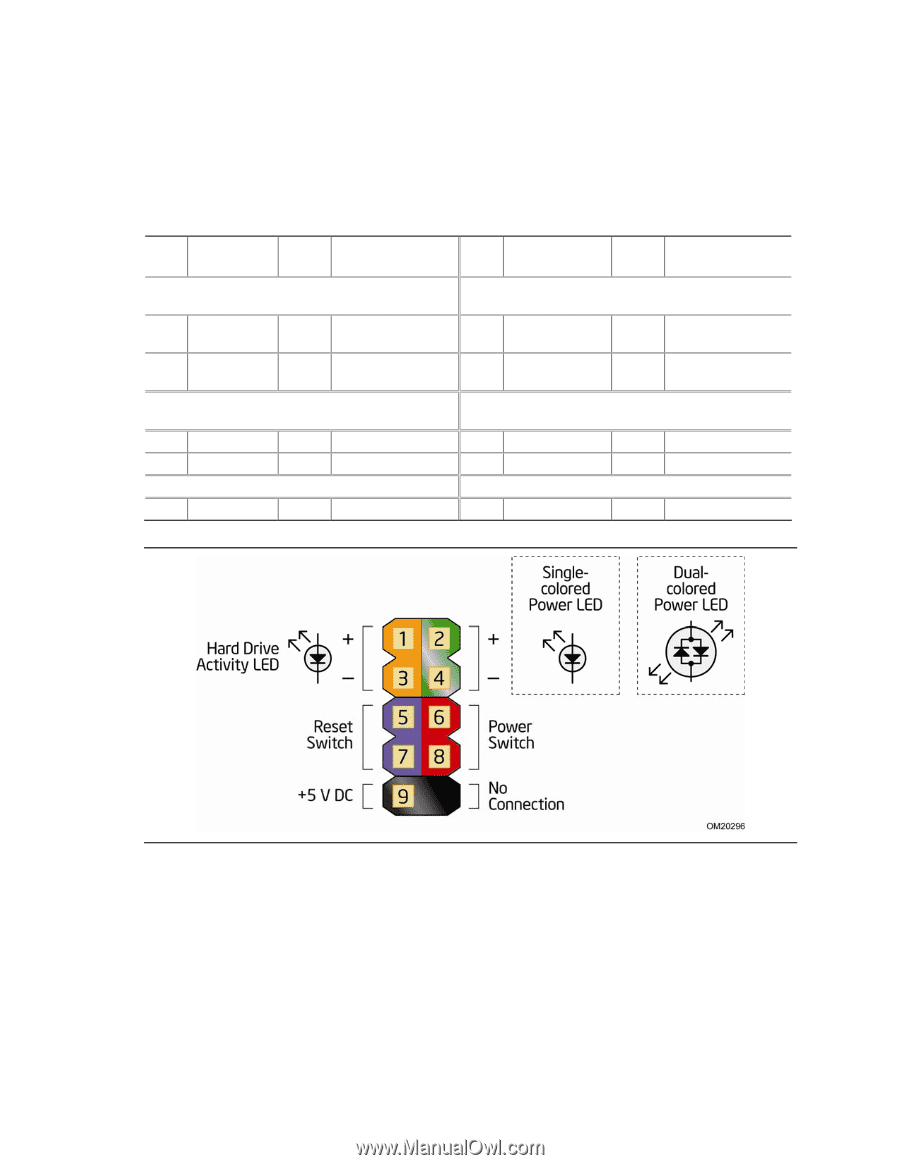
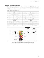
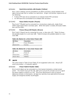
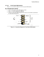
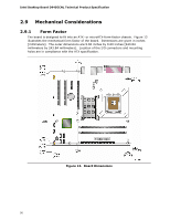
Technical Reference 2.7.2.4 Front Panel Header This section describes the functions of the front panel header. Table 23 lists the signal names of the front panel header. Figure 10 is a connection diagram for the front panel header. Table 23. Front Panel Header Pin Signal In/ Out Description Hard Drive Activity LED [Yellow] 1 HD_PWR Out Hard disk LED pull-up to +5 V 3 HDA# Out Hard disk active LED Reset Switch [Purple] 5 Ground Ground 7 FP_RESET# In Reset switch Power 9 +5 V Power Pin Signal In/ Out Description Power LED [Green] 2 HDR_BLNK_ Out Front panel green GRN LED 4 HDR_BLNK_ Out Front panel yellow YEL LED On/Off Switch [Red] 6 FPBUT_IN In Power switch 8 Ground Ground Not Connected 10 N/C Not connected Figure 10. Connection Diagram for Front Panel Header 51
-
 1
1 -
2
-
3
-
4
-
5
-
6
-
7
-
8
-
9
-
10
-
11
-
12
-
13
-
14
-
15
-
16
-
17
-
18
-
19
-
20
-
21
-
22
-
23
-
24
-
25
-
26
-
27
-
28
-
29
-
30
-
31
-
32
-
33
-
34
-
35
-
36
-
37
-
38
-
39
-
40
-
41
-
42
-
43
-
44
-
45
-
 46
46 -
 47
47 -
 48
48 -
 49
49 -
 50
50 -
 51
51 -
 52
52 -
 53
53 -
 54
54 -
 55
55 -
 56
56 -
57
-
58
-
59
-
60
-
61
-
62
-
63
-
64
-
65
-
66
-
67
-
68
-
69
-
70
-
71
-
72
-
73
-
74
-
75
-
76
-
77
-
78
-
79
-
80
-
81
-
82
-
83
-
84
-
85
-
86
-
87
-
88
-
89
-
90
 |
 |