Intel D945GCNL Product Specification - Page 58
Fan Header Current Capability, Add-in Board Considerations
 |
UPC - 735858194570
View all Intel D945GCNL manuals
Add to My Manuals
Save this manual to your list of manuals |
Page 58 highlights
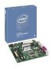
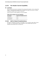
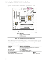
Intel Desktop Board D945GCNL Technical Product Specification 2.10.2 Fan Header Current Capability CAUTION The processor fan must be connected to the processor fan header, not to a chassis fan header. Connecting the processor fan to a chassis fan header may result in onboard component damage that will halt fan operation. Table 28 lists the current capability of the fan headers. Table 28. Fan Header Current Capability Fan Header Maximum Available Current Processor fan Front chassis fan Rear chassis fan 2.0 A 1.5 A 1.5 A 2.10.3 Add-in Board Considerations The board is designed to provide 2 A (average) of +5 V current for each add-in board. The total +5 V current draw for add-in boards for a fully loaded board (all three expansion slots filled) must not exceed 6 A. 58
-
 1
1 -
2
-
3
-
4
-
5
-
6
-
7
-
8
-
9
-
10
-
11
-
12
-
13
-
14
-
15
-
16
-
17
-
18
-
19
-
20
-
21
-
22
-
23
-
24
-
25
-
26
-
27
-
28
-
29
-
30
-
31
-
32
-
33
-
34
-
35
-
36
-
37
-
38
-
39
-
40
-
41
-
42
-
43
-
44
-
45
-
46
-
47
-
48
-
49
-
50
-
51
-
52
-
 53
53 -
 54
54 -
 55
55 -
 56
56 -
 57
57 -
 58
58 -
 59
59 -
 60
60 -
 61
61 -
 62
62 -
 63
63 -
64
-
65
-
66
-
67
-
68
-
69
-
70
-
71
-
72
-
73
-
74
-
75
-
76
-
77
-
78
-
79
-
80
-
81
-
82
-
83
-
84
-
85
-
86
-
87
-
88
-
89
-
90
 |
 |