Intel D946GZTS Product Guide - Page 16
RJ-45 LAN Connector LEDs, Hi-Speed USB 2.0 Support - usb driver
 |
UPC - 735858183536
View all Intel D946GZTS manuals
Add to My Manuals
Save this manual to your list of manuals |
Page 16 highlights
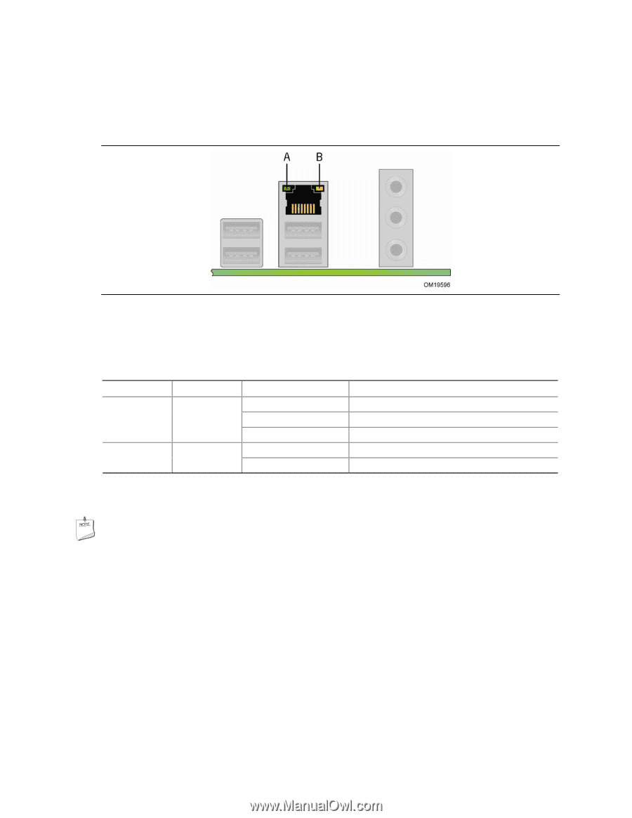
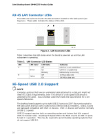
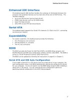
Intel Desktop Board D946GZTS Product Guide RJ-45 LAN Connector LEDs Two LEDs are built into the RJ-45 LAN connector located on the back panel (see Figure 2). These LEDs indicate the status of the LAN. Figure 2. LAN Connector LEDs Table 3 describes the LED states when the board is powered up and the LAN subsystem is operating. Table 3. LAN Connector LED States LED A B LED Color Green Yellow LED State Off On Blinking Off On Indicates LAN link is not established LAN link is established LAN activity is occurring 10 Mb/s data rate 100 Mb/s data rate Hi-Speed USB 2.0 Support NOTE Computer systems that have an unshielded cable attached to a USB port might not meet FCC Class B requirements, even if no device or a low-speed USB device is attached to the cable. Use a shielded cable that meets the requirements for a fullspeed USB device. The desktop board supports up to eight USB 2.0 ports via ICH7 (four ports routed to the back panel and four ports routed to two internal USB 2.0 headers). USB 2.0 ports are backward compatible with USB 1.1 devices. USB 1.1 devices will function normally at USB 1.1 speeds. USB 2.0 support requires both an operating system and drivers that fully support USB 2.0 transfer rates. Disabling Hi-Speed USB in the BIOS reverts all USB 2.0 ports to USB 1.1 operation. This may be required to accommodate operating systems that do not support USB 2.0. 16
-
 1
1 -
2
-
3
-
4
-
5
-
6
-
7
-
8
-
9
-
10
-
 11
11 -
 12
12 -
 13
13 -
 14
14 -
 15
15 -
 16
16 -
 17
17 -
 18
18 -
 19
19 -
 20
20 -
 21
21 -
22
-
23
-
24
-
25
-
26
-
27
-
28
-
29
-
30
-
31
-
32
-
33
-
34
-
35
-
36
-
37
-
38
-
39
-
40
-
41
-
42
-
43
-
44
-
45
-
46
-
47
-
48
-
49
-
50
-
51
-
52
-
53
-
54
-
55
-
56
-
57
-
58
-
59
-
60
-
61
-
62
-
63
-
64
-
65
-
66
-
67
-
68
-
69
-
70
-
71
-
72
-
73
-
74
-
75
-
76
 |
 |