Intel D946GZTS Product Guide - Page 29
Lift the Load Plate, Remove the Protective Socket Cover
 |
UPC - 735858183536
View all Intel D946GZTS manuals
Add to My Manuals
Save this manual to your list of manuals |
Page 29 highlights
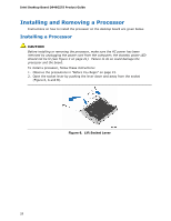
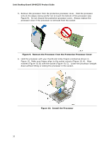
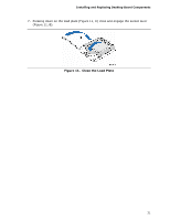
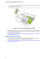
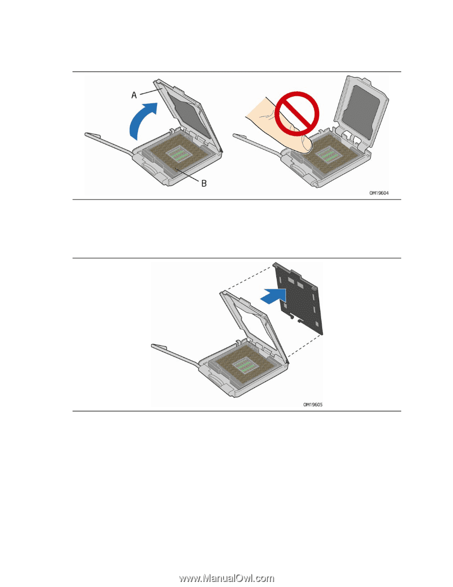
Installing and Replacing Desktop Board Components 3. Lift the load plate (Figure 7, A). Do not touch the socket contacts (Figure 7, B). Figure 7. Lift the Load Plate 4. Remove the plastic protective socket cover from the load plate (see Figure 8). Do not discard the protective socket cover. Always replace the socket cover if the processor is removed from the socket. Figure 8. Remove the Protective Socket Cover 29
-
 1
1 -
2
-
3
-
4
-
5
-
6
-
7
-
8
-
9
-
10
-
11
-
12
-
13
-
14
-
15
-
16
-
17
-
18
-
19
-
20
-
21
-
22
-
23
-
 24
24 -
 25
25 -
 26
26 -
 27
27 -
 28
28 -
 29
29 -
 30
30 -
 31
31 -
 32
32 -
 33
33 -
 34
34 -
35
-
36
-
37
-
38
-
39
-
40
-
41
-
42
-
43
-
44
-
45
-
46
-
47
-
48
-
49
-
50
-
51
-
52
-
53
-
54
-
55
-
56
-
57
-
58
-
59
-
60
-
61
-
62
-
63
-
64
-
65
-
66
-
67
-
68
-
69
-
70
-
71
-
72
-
73
-
74
-
75
-
76
 |
 |
Installing and Replacing Desktop Board Components
29
3.
Lift the load plate (Figure 7, A).
Do not touch the socket contacts (Figure 7, B).
Figure 7.
Lift the Load Plate
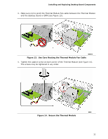
4.
Remove the plastic protective socket cover from the load plate (see Figure 8).
Do
not discard the protective socket cover.
Always replace the socket cover if the
processor is removed from the socket.
Figure 8.
Remove the Protective Socket Cover