Intel DG33BU Product Guide - Page 22
V Standby Power Indicator LED, Location of the Standby Power Indicator, Related Links - memory capacity
 |
UPC - 735858192095
View all Intel DG33BU manuals
Add to My Manuals
Save this manual to your list of manuals |
Page 22 highlights
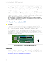
Intel Desktop Board DG33BU Product Guide Power supplies used with this Desktop Board must be able to provide enough standby current to support the standard Instantly Available (ACPI S3 sleep state) configuration. If the standby current necessary to support multiple wake events from the PCI and/or USB buses exceeds power supply capacity, the Desktop Board may lose register settings stored in memory. Instantly Available PC technology enables the board to enter the ACPI S3 (Suspend-toRAM) sleep state. While in the S3 sleep state, the computer will appear to be off. If the computer has a dual-colored power LED on the front panel, the sleep state is indicated by the LED turning amber. When signaled by a wake-up device or event, the computer quickly returns to its last known awake state. The Desktop Board supports the PCI Bus Power Management Interface Specification. Add-in cards that support this specification can participate in power management and can be used to wake the computer. +5 V Standby Power Indicator LED CAUTION If the AC power has been switched off and the standby power indicator is still lit, disconnect the power cord before installing or removing any devices connected to the board. Failure to do so could damage the board and any attached devices. The Desktop Board's standby power indicator, shown in Figure 3, is lit when there is standby power still present on the board even when the computer appears to be off. For example, when this LED is lit, standby power is still present at the memory module sockets and the PCI bus connectors. Figure 3. Location of the Standby Power Indicator Related Links: For more information on standby current requirements for the Desktop Board, refer to the Technical Product Specification by going to the following link, finding the product, and selecting Product Documentation from the left-hand menu: http://support.intel.com/support/motherboards/desktop/ 22
-
 1
1 -
2
-
3
-
4
-
5
-
6
-
7
-
8
-
9
-
10
-
11
-
12
-
13
-
14
-
15
-
16
-
 17
17 -
 18
18 -
 19
19 -
 20
20 -
 21
21 -
 22
22 -
 23
23 -
 24
24 -
 25
25 -
 26
26 -
 27
27 -
28
-
29
-
30
-
31
-
32
-
33
-
34
-
35
-
36
-
37
-
38
-
39
-
40
-
41
-
42
-
43
-
44
-
45
-
46
-
47
-
48
-
49
-
50
-
51
-
52
-
53
-
54
-
55
-
56
-
57
-
58
-
59
-
60
-
61
-
62
-
63
-
64
-
65
-
66
-
67
-
68
-
69
-
70
-
71
-
72
-
73
-
74
-
75
 |
 |
