Intel DG41TY Product Guide - Page 47
Serial Port Header, HD Audio Link Header
 |
UPC - 735858204392
View all Intel DG41TY manuals
Add to My Manuals
Save this manual to your list of manuals |
Page 47 highlights
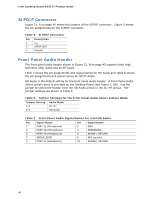
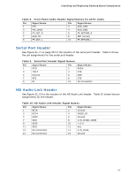
Installing and Replacing Desktop Board Components Table 8. Front Panel Audio Header Signal Names for AC'97 Audio Pin Signal Name 1 MIC 3 MIC_BIAS 5 FP_OUT_R 7 AUD_5V 9 FP_OUT_L Pin Signal Name 2 AUD_GND 4 AUD_GND 6 FP_RETURN_R 8 KEY (no pin) 10 FP_RETURN_L Serial Port Header See Figure 21, C on page 45 for the location of the serial port header. Table 9 shows the pin assignments for the serial port header. Table 9. Serial Port Header Signal Names Pin Signal Name 1 DCD 3 TXD# 5 Ground 7 RTS 9 RI Pin Signal Name 2 RXD# 4 DTR 6 DSR 8 CTS 10 No Connection HD Audio Link Header See Figure 21, D for the location of the HD Audio Link header. Table 10 shows the pin assignments for the header. Table 10. HD Audio Link Header Signal Names Pin Signal Name 1 BCLK 3 RST# 5 SYNC 7 SDO 9 SDI0 11 SDI1 13 No Connection 15 No Connection Pin Signal Name 2 Ground 4 DVDD_IO 6 Ground 8 3.3V_DVDD_CORE 10 +12 V 12 Key 14 3.3V_DUAL 16 Ground 47
-
 1
1 -
2
-
3
-
4
-
5
-
6
-
7
-
8
-
9
-
10
-
11
-
12
-
13
-
14
-
15
-
16
-
17
-
18
-
19
-
20
-
21
-
22
-
23
-
24
-
25
-
26
-
27
-
28
-
29
-
30
-
31
-
32
-
33
-
34
-
35
-
36
-
37
-
38
-
39
-
40
-
41
-
 42
42 -
 43
43 -
 44
44 -
 45
45 -
 46
46 -
 47
47 -
 48
48 -
 49
49 -
 50
50 -
 51
51 -
 52
52 -
53
-
54
-
55
-
56
-
57
-
58
-
59
-
60
-
61
-
62
-
63
-
64
-
65
-
66
-
67
-
68
-
69
-
70
-
71
-
72
-
73
-
74
-
75
-
76
 |
 |