Intel DG41TY Product Guide - Page 48
Chassis Intrusion Header, Front Panel Header, Table 12. Front Panel Header
 |
UPC - 735858204392
View all Intel DG41TY manuals
Add to My Manuals
Save this manual to your list of manuals |
Page 48 highlights
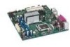
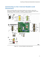
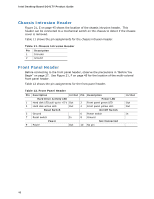
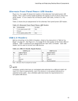
Intel Desktop Board DG41TY Product Guide Chassis Intrusion Header Figure 21, E on page 45 shows the location of the chassis intrusion header. This header can be connected to a mechanical switch on the chassis to detect if the chassis cover is removed. Table 11 shows the pin assignments for the chassis intrusion header. Table 11. Chassis Intrusion Header Pin Description 1 Intruder 2 Ground Front Panel Header Before connecting to the front panel header, observe the precautions in "Before You Begin" on page 27. See Figure 21, F on page 45 for the location of the multi-colored front panel header. Table 12 shows the pin assignments for the front panel header. Table 12. Front Panel Header Pin Description In/Out Pin Description Hard Drive Activity LED Power LED 1 Hard disk LED pull-up to +5 V Out 3 Hard disk active LED Out 2 Front panel green LED 4 Front panel yellow LED Reset Switch On/Off Switch 5 Ground 7 Reset switch 6 Power switch In 8 Ground Power Not Connected 9 Power Out 10 No pin In/Out Out Out In 48
-
 1
1 -
2
-
3
-
4
-
5
-
6
-
7
-
8
-
9
-
10
-
11
-
12
-
13
-
14
-
15
-
16
-
17
-
18
-
19
-
20
-
21
-
22
-
23
-
24
-
25
-
26
-
27
-
28
-
29
-
30
-
31
-
32
-
33
-
34
-
35
-
36
-
37
-
38
-
39
-
40
-
41
-
42
-
 43
43 -
 44
44 -
 45
45 -
 46
46 -
 47
47 -
 48
48 -
 49
49 -
 50
50 -
 51
51 -
 52
52 -
 53
53 -
54
-
55
-
56
-
57
-
58
-
59
-
60
-
61
-
62
-
63
-
64
-
65
-
66
-
67
-
68
-
69
-
70
-
71
-
72
-
73
-
74
-
75
-
76
 |
 |