Intel DG43GT Product Guide - Page 36
Installing and Removing Memory, Guidelines for Dual Channel Memory Configuration
 |
UPC - 735858209175
View all Intel DG43GT manuals
Add to My Manuals
Save this manual to your list of manuals |
Page 36 highlights
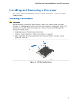
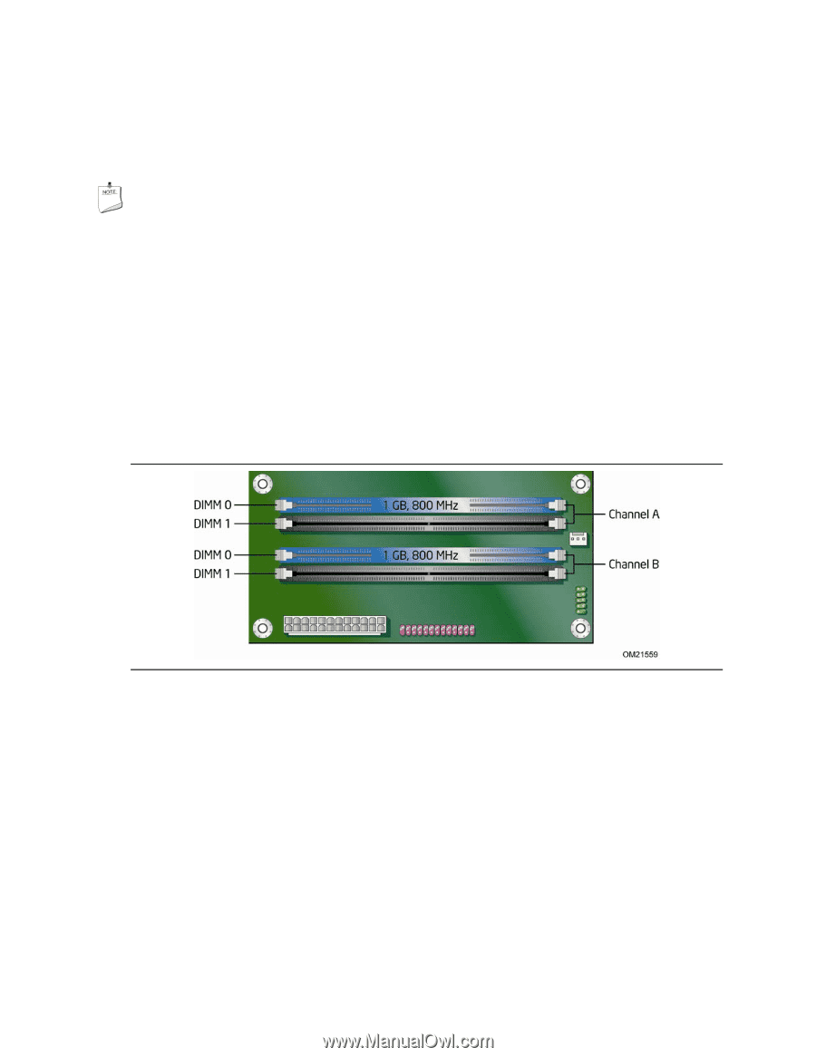
Intel Desktop Board DG43GT Product Guide Installing and Removing Memory Intel Desktop board DG43GT has four 240-pin DDR2 DIMM sockets arranged as DIMM 0 and DIMM 1 in both Channel A and Channel B. NOTE Regardless of the memory configuration used (dual or single channel), Channel A, DIMM 0 must always be populated. This is a requirement of the ICH10 Manageability Engine feature. Guidelines for Dual Channel Memory Configuration Before installing DIMMs, read and follow these guidelines for dual channel configuration. Two or Four DIMMs Install a matched pair of DIMMs equal in speed and size (see Figure 13) in DIMM 0 (blue) of channels A and B. Figure 13. Dual Channel Memory Configuration with Two DIMMs 36
-
 1
1 -
2
-
3
-
4
-
5
-
6
-
7
-
8
-
9
-
10
-
11
-
12
-
13
-
14
-
15
-
16
-
17
-
18
-
19
-
20
-
21
-
22
-
23
-
24
-
25
-
26
-
27
-
28
-
29
-
30
-
 31
31 -
 32
32 -
 33
33 -
 34
34 -
 35
35 -
 36
36 -
 37
37 -
 38
38 -
 39
39 -
 40
40 -
 41
41 -
42
-
43
-
44
-
45
-
46
-
47
-
48
-
49
-
50
-
51
-
52
-
53
-
54
-
55
-
56
-
57
-
58
-
59
-
60
-
61
-
62
-
63
-
64
-
65
-
66
-
67
-
68
-
69
-
70
-
71
-
72
-
73
-
74
-
75
-
76
-
77
-
78
-
79
-
80
-
81
-
82
 |
 |
Intel Desktop Board DG43GT Product Guide
36
Installing and Removing Memory
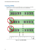
Intel Desktop board DG43GT has four 240-pin DDR2 DIMM sockets arranged as
DIMM 0 and DIMM 1 in both Channel A and Channel B.
NOTE
Regardless of the memory configuration used (dual or single channel), Channel A,
DIMM 0 must always be populated.
This is a requirement of the ICH10 Manageability
Engine feature.
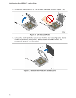
Guidelines for Dual Channel Memory Configuration
Before installing DIMMs, read and follow these guidelines for dual channel
configuration.
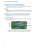
Two or Four DIMMs
Install a matched pair of DIMMs equal in speed and size (see Figure 13) in DIMM 0
(blue) of channels A and B.
Figure 13.
Dual Channel Memory Configuration with Two DIMMs