Intel DP43BF Product Guide - Page 48
HD Audio Link Header, USB 2.0 Headers, Table 11. HD Audio Link Header Signal Names
 |
View all Intel DP43BF manuals
Add to My Manuals
Save this manual to your list of manuals |
Page 48 highlights
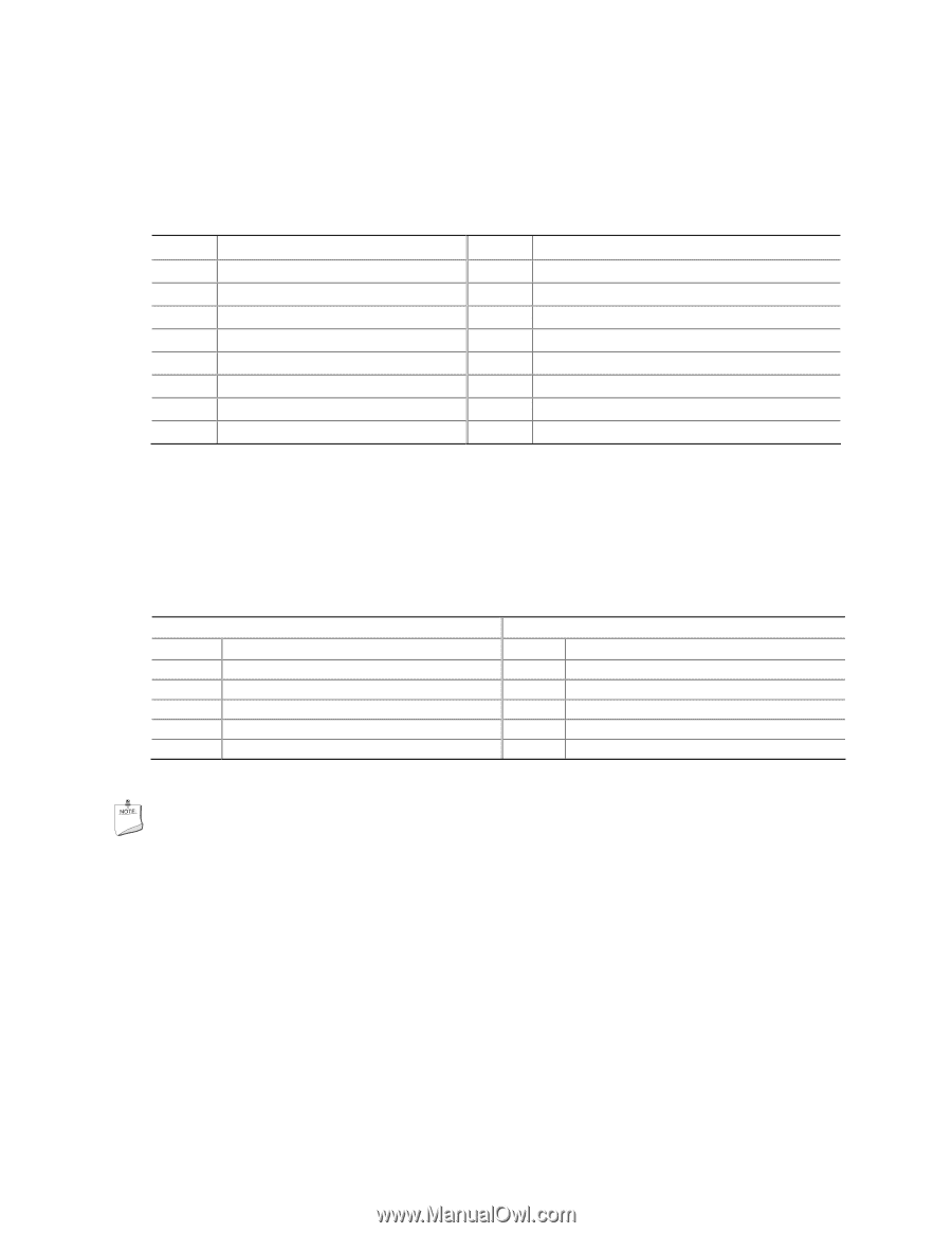
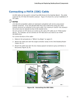
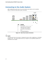
Intel Desktop Board DP43BF Product Guide HD Audio Link Header See Figure 22, F for the location of the HD Audio Link header. Table 11 shows the pin assignments for the header. Table 11. HD Audio Link Header Signal Names Pin Signal Name 1 BCLK 3 RST# Pin Signal Name 2 Ground 4 3.3 Vcc 5 SYNC 6 Ground 7 SDO 9 SDI0 11 SDI1 8 3.3 Vcc 10 +12 V 12 Key 13 No Connection 14 3.3 V STBY 15 No Connection 16 Ground USB 2.0 Headers See Figure 22, G for the location of the three USB 2.0 headers. Table 12 shows the pin assignments for each USB 2.0 header. Each USB header can be used to connect two USB devices. Table 12. USB 2.0 Header Signal Names USB Port A Pin Signal Name Pin 1 Power (+5 V) 2 3 D- 4 5 D+ 6 7 Ground 8 9 Key 10 Note: USB ports may be assigned as needed. USB Port B Signal Name Power (+5 V) DD+ Ground No Connection NOTE Computer systems that have an unshielded cable attached to a USB port might not meet FCC Class B requirements, even if no device or a low-speed USB device is attached to the cable. Use a shielded cable that meets the requirements for a full-speed USB device. 48
-
 1
1 -
2
-
3
-
4
-
5
-
6
-
7
-
8
-
9
-
10
-
11
-
12
-
13
-
14
-
15
-
16
-
17
-
18
-
19
-
20
-
21
-
22
-
23
-
24
-
25
-
26
-
27
-
28
-
29
-
30
-
31
-
32
-
33
-
34
-
35
-
36
-
37
-
38
-
39
-
40
-
41
-
42
-
 43
43 -
 44
44 -
 45
45 -
 46
46 -
 47
47 -
 48
48 -
 49
49 -
 50
50 -
 51
51 -
 52
52 -
 53
53 -
54
-
55
-
56
-
57
-
58
-
59
-
60
-
61
-
62
-
63
-
64
-
65
-
66
-
67
-
68
-
69
-
70
-
71
-
72
-
73
-
74
-
75
-
76
-
77
-
78
 |
 |