Intel DQ43AP Product Specification - Page 21
Serial ATA Interfaces
 |
View all Intel DQ43AP manuals
Add to My Manuals
Save this manual to your list of manuals |
Page 21 highlights
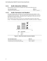
Product Description 1.6.1.4 Digital Visual Interface (DVI) The DVI-D port supports digital DVI displays. The maximum supported resolution is 2048 x 1536 at 75 Hz refresh (QXGA). The DVI-D port is compliant with the DVI 1.0 specification. 1.6.2 USB The board supports up to eight USB 2.0 ports, supports UHCI and EHCI, and uses UHCI- and EHCI-compatible drivers. The ICH10D provides the USB controller for all ports. The port arrangement is as follows: • Four ports are implemented with stacked back panel connectors • Four ports are routed to two separate front panel USB headers For information about The location of the USB connectors on the back panel The location of the front panel USB headers Refer to Figure 9, page 43 Figure 10, page 44 1.6.3 Serial ATA Interfaces The board provides two Serial ATA (SATA) connectors, which support one device per connector. The board also provides one red external Serial ATA (eSATA) connector. 1.6.3.1 Serial ATA Support The board's Serial ATA controller offers three independent Serial ATA ports with a theoretical maximum transfer rate of 3 Gbits/sec per port. One device can be installed on each port for a maximum of three Serial ATA devices. A point-to-point interface is used for host to device connections, unlike Parallel ATA which supports a master/slave configuration and two devices per channel. For compatibility, the underlying Serial ATA functionality is transparent to the operating system. The Serial ATA controller can operate in both legacy and native modes. In legacy mode, standard IDE I/O and IRQ resources are assigned (IRQ 14 and 15). In Native mode, standard PCI Conventional bus resource steering is used. Native mode is the preferred mode for configurations using the Windows* XP and Windows Vista operating systems. NOTE Many Serial ATA drives use new low-voltage power connectors and require adapters or power supplies equipped with low-voltage power connectors. For more information, see: http://www.serialata.org/. For information about The location of the Serial ATA connectors Refer to Figure 10, page 44 21
-
 1
1 -
2
-
3
-
4
-
5
-
6
-
7
-
8
-
9
-
10
-
11
-
12
-
13
-
14
-
15
-
 16
16 -
 17
17 -
 18
18 -
 19
19 -
 20
20 -
 21
21 -
 22
22 -
 23
23 -
 24
24 -
 25
25 -
 26
26 -
27
-
28
-
29
-
30
-
31
-
32
-
33
-
34
-
35
-
36
-
37
-
38
-
39
-
40
-
41
-
42
-
43
-
44
-
45
-
46
-
47
-
48
-
49
-
50
-
51
-
52
-
53
-
54
-
55
-
56
-
57
-
58
-
59
-
60
-
61
-
62
-
63
-
64
-
65
-
66
-
67
-
68
-
69
-
70
-
71
-
72
-
73
-
74
-
75
-
76
-
77
-
78
-
79
-
80
-
81
-
82
-
83
-
84
-
85
-
86
-
87
-
88
-
89
-
90
 |
 |