Intel DQ43AP Product Specification - Page 51
Alternate Front Panel Power LED Header, 2.2.6, Intel AMT M State LED
 |
View all Intel DQ43AP manuals
Add to My Manuals
Save this manual to your list of manuals |
Page 51 highlights
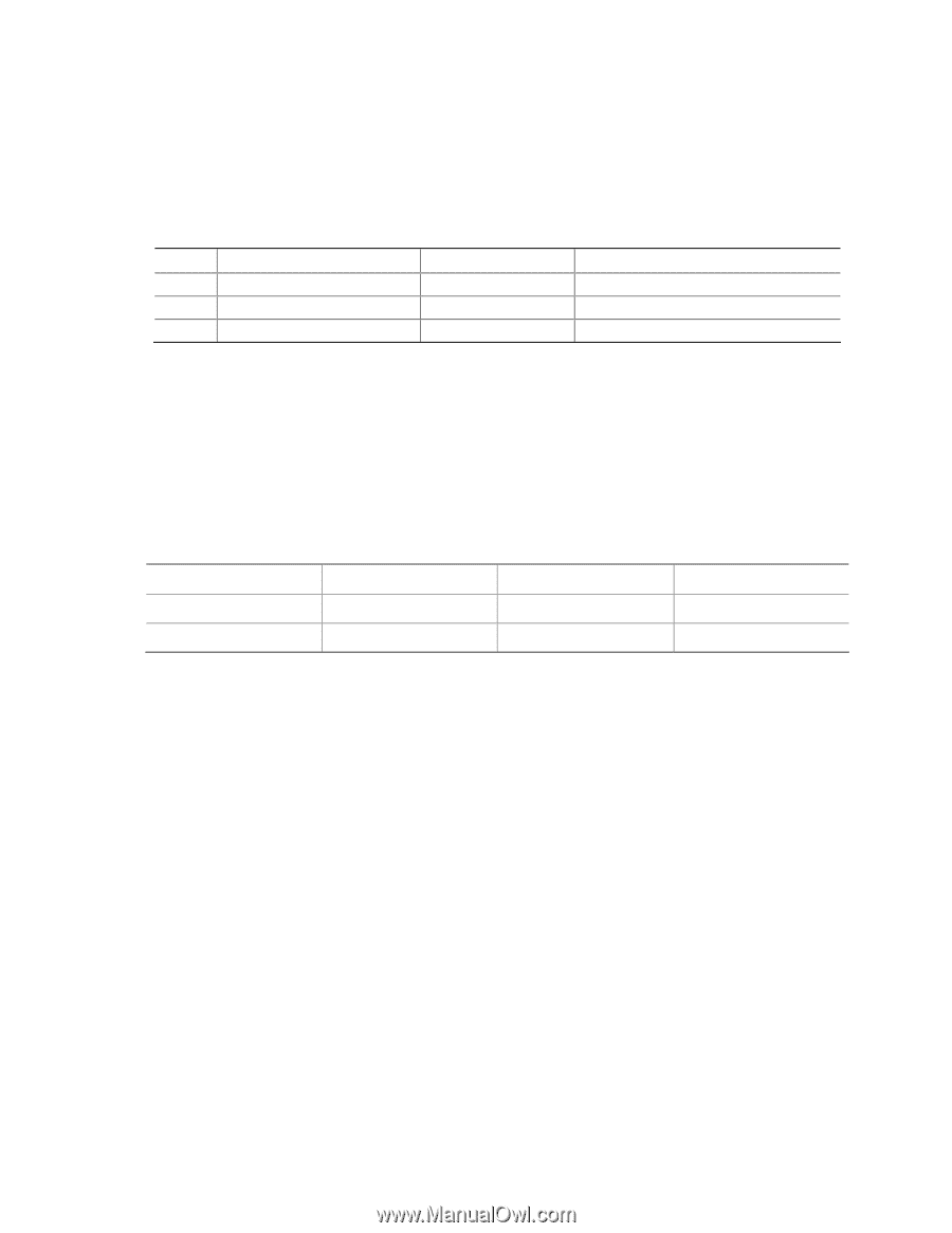
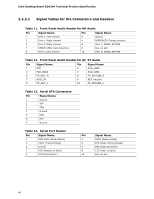
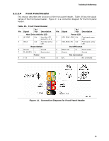
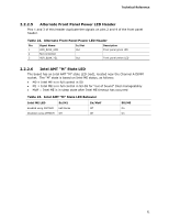
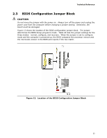
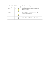
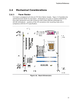
Technical Reference 2.2.2.5 Alternate Front Panel Power LED Header Pins 1 and 3 of this header duplicate the signals on pins 2 and 4 of the front panel header. Table 22. Alternate Front Panel Power LED Header Pin Signal Name 1 HDR_BLNK_GRN 2 Not connected 3 HDR_BLNK_YEL In/Out Out Out Description Front panel green LED Front panel yellow LED 2.2.2.6 Intel AMT "M" State LED The board has an Intel AMT "M" state LED (red), located near the Channel A DIMM socket. The "M" state is based on Intel ME status, as follows: • M0 = Intel ME is in full control in S0 • M1 = Intel ME is in full control in S3-S5 for "out of bound" Intel manageability • Moff = Intel ME is in sleep state after Intel ME timeout has occurred Table 23. Intel AMT "M" State LED Behavior Intel ME LED Sx/M1 Sx/Moff Enabled using AMTNVM LED blinks Off Disabled using AMTNVM Off Off S0/M0 On On 51
-
 1
1 -
2
-
3
-
4
-
5
-
6
-
7
-
8
-
9
-
10
-
11
-
12
-
13
-
14
-
15
-
16
-
17
-
18
-
19
-
20
-
21
-
22
-
23
-
24
-
25
-
26
-
27
-
28
-
29
-
30
-
31
-
32
-
33
-
34
-
35
-
36
-
37
-
38
-
39
-
40
-
41
-
42
-
43
-
44
-
45
-
 46
46 -
 47
47 -
 48
48 -
 49
49 -
 50
50 -
 51
51 -
 52
52 -
 53
53 -
 54
54 -
 55
55 -
 56
56 -
57
-
58
-
59
-
60
-
61
-
62
-
63
-
64
-
65
-
66
-
67
-
68
-
69
-
70
-
71
-
72
-
73
-
74
-
75
-
76
-
77
-
78
-
79
-
80
-
81
-
82
-
83
-
84
-
85
-
86
-
87
-
88
-
89
-
90
 |
 |