Intel DX79TO Technical Product Specification - Page 29
Thermal Monitoring
 |
View all Intel DX79TO manuals
Add to My Manuals
Save this manual to your list of manuals |
Page 29 highlights
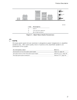
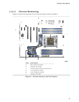
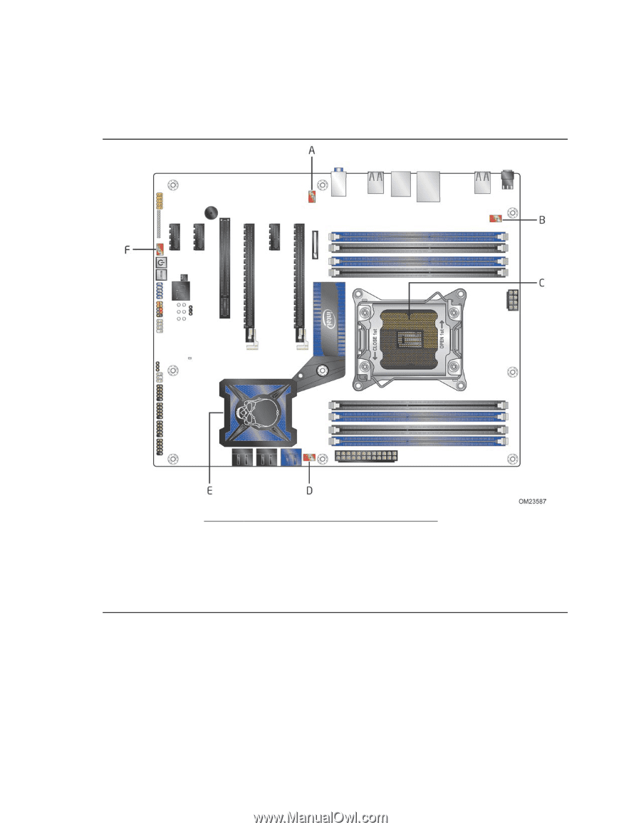
Product Description 1.11.4 Thermal Monitoring Figure 6 shows the locations of the thermal sensors and fan headers. Item A B C D E F Description Rear chassis fan header Processor fan header Thermal diode, located on processor die Front chassis fan header Intel X79 Express Chipset Auxiliary fan header Figure 6. Thermal Sensors and Fan Headers 29
-
 1
1 -
2
-
3
-
4
-
5
-
6
-
7
-
8
-
9
-
10
-
11
-
12
-
13
-
14
-
15
-
16
-
17
-
18
-
19
-
20
-
21
-
22
-
23
-
 24
24 -
 25
25 -
 26
26 -
 27
27 -
 28
28 -
 29
29 -
 30
30 -
 31
31 -
 32
32 -
 33
33 -
 34
34 -
35
-
36
-
37
-
38
-
39
-
40
-
41
-
42
-
43
-
44
-
45
-
46
-
47
-
48
-
49
-
50
-
51
-
52
-
53
-
54
-
55
-
56
-
57
-
58
-
59
-
60
-
61
-
62
-
63
-
64
-
65
-
66
-
67
-
68
-
69
-
70
-
71
-
72
-
73
-
74
-
75
-
76
-
77
-
78
-
79
-
80
-
81
-
82
-
83
-
84
-
85
-
86
-
87
-
88
-
89
-
90
-
91
-
92
-
93
-
94
 |
 |
Product Description
29
1.11.4
Thermal Monitoring
Figure 6 shows the locations of the thermal sensors and fan headers.
Item
Description
A
Rear chassis fan header
B
Processor fan header
C
Thermal diode, located on processor die
D
Front chassis fan header
E
Intel X79 Express Chipset
F
Auxiliary fan header
Figure 6.
Thermal Sensors and Fan Headers