Intel RS25DB080 Hardware User Guide - Page 24
Table 1. Jumper Description, Jumper, Connector, Description - fastpath
 |
View all Intel RS25DB080 manuals
Add to My Manuals
Save this manual to your list of manuals |
Page 24 highlights
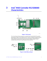
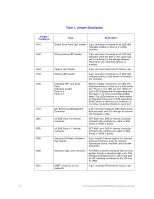
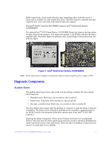
Table 1. Jumper Description s Jumper / Connector J1A1 J1A2 J1A3 J1A4 J1A5 J1A7 J2B1 J2B2 J2B3 J2B4 J5A1 Type Description Global Drive Fault LED header 2-pin connector Connects to an LED that indicates whether a drive is in a fault condition. Write-pending LED header 2-pin connector Connects to an LED that indicates when the data in the cache has yet to be written to the storage devices. Used when the write-back feature is enabled. Factory Test header 2-pin connector Reserved for factory use. Activity LED header 2-pin connector Connects to an LED that indicates activity on the drives connected to the controller. Individual PHY and Drive Fault Indication header Ports 0-3 Ports 4-7 2x8-pin header Connects to an LED that indicates whether a drive is in a fault condition. There is one LED per port. When lit, each LED indicates the corresponding drive has failed or is in the Unconfigured-Bad state. The LEDs function in a direct-attach configuration (there are no SAS expanders). Direct attach is defined as a maximum of one drive connected directly to each port. I2C Enclosure Management Connector 3-pin connector Supports SES (SCSI enclosure services) over I2C through an internal I2C backplane cable. x4 SAS Ports 0-3 internal connector SFF-8087 mini SAS 4i internal connector Connects the controller by cable to SAS drives or SATA 2 drives. x4 SAS Ports 4-7 internal connector SFF-8087 mini SAS 4i internal connector Connects the controller by cable to SAS drives or SATA 2 drives. Advanced Software Hardware Key Header 3-pin header Enables support for selected advanced features, such as recovery, Supersized cache, FastPath, and full disk encryption. Standard edge card connector The RAID controller interfaces with the host system though a standard edge card. This interface provides power to the board and an I2C interface connected to the I2C bus for IPMI. UART connector for the expander 4-pin connector Reserved for factory use. 14 Intel® RAID Controller RS25DB080 Hardware User's Guide
-
 1
1 -
2
-
3
-
4
-
5
-
6
-
7
-
8
-
9
-
10
-
11
-
12
-
13
-
14
-
15
-
16
-
17
-
18
-
 19
19 -
 20
20 -
 21
21 -
 22
22 -
 23
23 -
 24
24 -
 25
25 -
 26
26 -
 27
27 -
 28
28 -
 29
29 -
30
-
31
-
32
-
33
-
34
-
35
-
36
-
37
-
38
-
39
-
40
-
41
-
42
-
43
-
44
-
45
-
46
-
47
-
48
-
49
-
50
-
51
-
52
-
53
-
54
 |
 |