Intel RS25DB080 Hardware User Guide - Page 28
LED Placement and Function, SAS/SATA Connectors, SAS/SATA Connector Pin-out - compatibility
 |
View all Intel RS25DB080 manuals
Add to My Manuals
Save this manual to your list of manuals |
Page 28 highlights
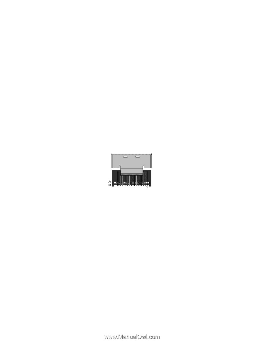
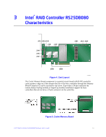
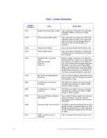
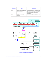
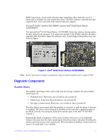
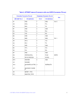
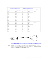
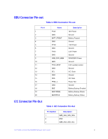
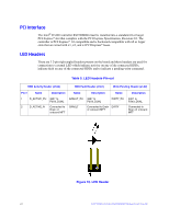
The rebuild alarm tone functions differently. It remains ON during the rebuild. After the rebuild completes, an alarm with a different tone sounds to signal that the rebuild is complete. This is a one-time, non-repeating tone. LED Placement and Function The Intel® RAID Controller RS25DB080 contains the following LEDs: • One surface-mounted heartbeat LED (Green Color) to indicate SAS2208 activity. • Another surface-mounted system error LED (Amber Color) to indicate a board error. SAS/SATA Connectors The Intel® Integrated RAID controller RS25DB080 provides two internal SFF8087 SAS/SATA signal connectors. Each SFF8087 connector provides support for four SAS/SATA ports. The sideband signals are configured to adhere to the SFF-8485 Specifications for SGPIO support. Internal connector Figure 8. Intel® RAID Controller RS25DB080 SAS/SATA Connectors SAS/SATA Connector Pin-out Signal names are with respect to the host; the device connected to the host reverses the signal names. Transmit pins connect to receive pins on the other device. The SAS/SATA connector is keyed at pin 1. These pin-outs for the serial ATA connector are not compatible with the legacy PATA connector. 18 Intel® RAID Controller RS25DB080 Hardware User's Guide
-
 1
1 -
2
-
3
-
4
-
5
-
6
-
7
-
8
-
9
-
10
-
11
-
12
-
13
-
14
-
15
-
16
-
17
-
18
-
19
-
20
-
21
-
22
-
 23
23 -
 24
24 -
 25
25 -
 26
26 -
 27
27 -
 28
28 -
 29
29 -
 30
30 -
 31
31 -
 32
32 -
 33
33 -
34
-
35
-
36
-
37
-
38
-
39
-
40
-
41
-
42
-
43
-
44
-
45
-
46
-
47
-
48
-
49
-
50
-
51
-
52
-
53
-
54
 |
 |