Intel RS2WG160 Hardware User Guide - Page 30
PCI Interface, LED Headers, Table 5. LED Headers Pin-out
 |
View all Intel RS2WG160 manuals
Add to My Manuals
Save this manual to your list of manuals |
Page 30 highlights
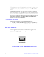
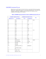
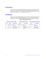
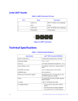
PCI Interface The Intel® RAID Controller RS2WG160 must be installed into a standard x8 or larger PCI Express* slot that complies with the PCI Express Specification, Revision 2.0. The controller is PCI Express* 1.0 compatible and is backward-compatible with x8 or larger slots that are wired with x1, x2, and x4 PCI Express* lanes. LED Headers There are 3 2-pin right angled headers present on the board and these headers are used for connection to external LED which indicate activity on any of the connected HDDs, indicate fault on any of the connected HDDs and to indicate a pending write command. Table 5. LED Headers Pin-out HDD Activity Header (JT4A1) HDD Fault Header (JT4A2) Write Pending Header (JT5A1) Pin # Name Description Name Description Name 1 D_ACTIVE_P 330? to GFAULT_PU 330? to U P3V3_DUAL P3V3_DUAL DIRTY_PU 2 D_ACTIVE_ Connected to GFAULT N Drain of Q3L1 Connected to Drain DIRTY of Q4B1 Description 330? to P3V3_DUAL Connected to Drain of Q2L1 20 Intel® RAID Controller RS2WG160 Hardware User's Guide
-
 1
1 -
2
-
3
-
4
-
5
-
6
-
7
-
8
-
9
-
10
-
11
-
12
-
13
-
14
-
15
-
16
-
17
-
18
-
19
-
20
-
21
-
22
-
23
-
24
-
 25
25 -
 26
26 -
 27
27 -
 28
28 -
 29
29 -
 30
30 -
 31
31 -
 32
32 -
 33
33 -
 34
34 -
 35
35 -
36
-
37
-
38
-
39
-
40
-
41
-
42
-
43
-
44
-
45
-
46
-
47
-
48
-
49
-
50
-
51
-
52
 |
 |