Intel S3000AH User Guide - Page 30
Configuration Jumpers - bios update
 |
UPC - 735858185806
View all Intel S3000AH manuals
Add to My Manuals
Save this manual to your list of manuals |
Page 30 highlights
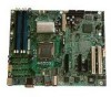
Configuration Jumpers NIC1 NVM 3 Protect Mode 2 J4A1 Update Default CMOS CLR 2 J1G3 3 Default CLEAR CMOS System Maintenance 3 Mode 2 J1H3 Default Remove jumper for BIOS recovery AF000525 Jumper Name NIC1 NVM Protect Mode CMOS Clear System Maintenance Mode Jumper Purpose Jumper in default position (pins 1-2) protects the Intel® 82573E/V firmware from being programmed. Jumper in update mode (pins 2-3) allows the Intel® 82573E/V firmware to be programmed. Jumper in normal position (pins 1-2) allows the system to successfully POST and boot to the OS environment. BIOS settings are kept intact. Jumper in clear position (pins 2-3) initiates a clearing of NVRAM following POST. A system message confirms the CMOS clear operation was successful. This setting enforces default BIOS settings, which can be changed by entering setup via F2, then exiting setup via F10 and saving changes. Jumper in normal position (pins 1-2) allows normal system operation with correct BIOS settings. System will POST normally. Jumper in maintenance mode (pins 2-3) allows Intel® AMT setting/ password reset. Jumper removed is used to recover from a corrupted BIOS. Bootable media with a valid BIOS ROM required. Figure 6. Configuration Jumper Descriptions 12 Intel® Server Board S3000AH User's Guide
-
 1
1 -
2
-
3
-
4
-
5
-
6
-
7
-
8
-
9
-
10
-
11
-
12
-
13
-
14
-
15
-
16
-
17
-
18
-
19
-
20
-
21
-
22
-
23
-
24
-
 25
25 -
 26
26 -
 27
27 -
 28
28 -
 29
29 -
 30
30 -
 31
31 -
 32
32 -
 33
33 -
 34
34 -
 35
35 -
36
-
37
-
38
-
39
-
40
-
41
-
42
-
43
-
44
-
45
-
46
-
47
-
48
-
49
-
50
-
51
-
52
-
53
-
54
-
55
-
56
-
57
-
58
-
59
-
60
-
61
-
62
-
63
-
64
-
65
-
66
-
67
-
68
-
69
-
70
-
71
-
72
-
73
-
74
 |
 |
