Intel S815EBM1 Quick Start Guide
Intel S815EBM1 - Server Board Motherboard Manual
 |
UPC - 735858149839
View all Intel S815EBM1 manuals
Add to My Manuals
Save this manual to your list of manuals |
Intel S815EBM1 manual content summary:
- Intel S815EBM1 | Quick Start Guide - Page 1
estão disponíveis em: http://support.intel.com/support/motherboards/server/S815EBM1/manual.htm All rights reserved. No part of this document may be copied, or reproduced in any form, or by any means without prior written consent of Intel. Intel Corporation (Intel) makes no warranty of any kind - Intel S815EBM1 | Quick Start Guide - Page 2
strap and attaching it to a metal part of the server chassis. Items Provided on the Bootable CD-ROM Intel Server Board S815EBM1 Product Guide Software utilities Server Product Information Customer Support Information Web Links To view the product guide, boot to Windows† 95/Windows NT† / Windows 98 - Intel S815EBM1 | Quick Start Guide - Page 3
of qualified memory and chassis components, as well as the latest list of supported processors see http://support.intel.com/support/motherboards/server/S815EBM1/compat.htm Processor Intel® Pentium® III processor or Intel® Celeron™ processor. ✏ NOTE While the board will electrically support all the - Intel S815EBM1 | Quick Start Guide - Page 4
condition exists, however, the BIOS will not pause on subsequent detection. Setup displays the installed memory configuration and shows memory above 512 MB as "not supported. Please see the S815EBM1 Technical Product Specification for more details. 4 Intel Server Board S815EBM1 Quick Start Guide - Intel S815EBM1 | Quick Start Guide - Page 5
+5V IRRX Ground IRTX 31 2-pin alternate power LED/Sleep connector 15 16 +5V Ground No Connection IH G HD LED 1 J9H3 2 Power LED On OM13571 Intel Server Board S815EBM1 Quick Start Guide 5 - Intel S815EBM1 | Quick Start Guide - Page 6
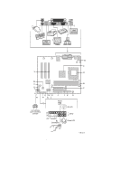
panel switch/LED connector R. Chassis intrusion connector S. Alternate front panel power LED connector T. System fan (fan 2) U. BIOS configuration jumper block V. Wake on LAN technology connector W. 4 Mbit Firmware Hub (FWH) X. PCI expansion slots 6 Intel Server Board S815EBM1 Quick Start Guide - Intel S815EBM1 | Quick Start Guide - Page 7
, purple C. USB port 1 D. USB port 3 E. Parallel port, burgundy F. VGA port, blue G. Serial port A, teal H. RJ-45 LAN connector with LED display I. USB port 0 J. USB port 2 7 Intel Server Board S815EBM1 Quick Start Guide - Intel S815EBM1 | Quick Start Guide - Page 8
Front Panel Connectors 31 A J9H4 B CD 15 1 16 2 I HG F E 15 1 16 J9H3 2 A. Chassis intrusion connector B. Reserved C. Reset switch D. Hard drive activity LED E. Power LED F. On/Off Switch G. No connect H. Ground I. +5 V OM12281 8 Intel Server Board S815EBM1 Quick Start Guide - Intel S815EBM1 | Quick Start Guide - Page 9
1 The BIOS uses current configuration information and passwords for booting. 1 After the POST runs, Setup runs automatically. The maintenance menu is displayed. 1 The BIOS attempts to recover the BIOS configuration. A recovery diskette is required. Intel Server Board S815EBM1 Quick Start Guide 9 - Intel S815EBM1 | Quick Start Guide - Page 10
compatible with this board by checking this URL: http://support.intel.com/support/motherboards/server/S815EBM1/ compat.htm Also note that the thermal solution provided with this board is designed only for use with processors that have an IHS. I II 10 Intel Server Board S815EBM1 Quick Start Guide - Intel S815EBM1 | Quick Start Guide - Page 11
III IV Intel Server Board S815EBM1 Quick Start Guide 11 - Intel S815EBM1 | Quick Start Guide - Page 12
V 12 Intel Server Board S815EBM1 Quick Start Guide - Intel S815EBM1 | Quick Start Guide - Page 13
Memory The S815EBM1 board requires that DIMMs be installed as shown in the following figure. The three DIMM sockets are arranged as Banks 0, 1, and 2 as shown. If installing a single DIMM, install it in Bank 0. If installing two DIMMs, install them in Banks 0 and 1. 0 1 2 OM12202 Intel Server Board - Intel S815EBM1 | Quick Start Guide - Page 14
promotes correct airflow within the chassis. Install the I/O shield before installing the server board in the chassis. Place the shield inside the chassis and press the shield ] 2.079 [52.804] 3.219 [81.768] 5.010 [127.25] Pictorial View OM12390 14 Intel Server Board S815EBM1 Quick Start Guide - Intel S815EBM1 | Quick Start Guide - Page 15
to your chassis manual for specific instructions on installing and removing the server board. Secure the server board to the chassis standoffs using six screws. Insert the screws into the mounting holes as shown in the following figure. OM12203 Intel Server Board S815EBM1 Quick Start Guide 15 - Intel S815EBM1 | Quick Start Guide - Page 16
IDE Drives The Intel® boxed server board package includes a 40-contact or 80-conductor IDE cable. It is capable of connecting two drives to the server board. The cable supports the Ultra UDMA- to the drive (i.e. the one labeled P3). B A OM12205 16 Intel Server Board S815EBM1 Quick Start Guide - Intel S815EBM1 | Quick Start Guide - Page 17
&T) Peru 0-800-50000, 800-628-8686 (via AT&T) Uruguay 000-410, 800-628-8686 (via AT&T) * Or contact your local dealer or distributor. For an updated list of telephone numbers, please see: http://www.intel.com/support/9089.htm Intel Server Board S815EBM1 Quick Start Guide 17 - Intel S815EBM1 | Quick Start Guide - Page 18
America), the Genuine Intel Dealer Program (Asia-Pacific Region), or the Intel Product Integrator Program (Europe/Latin America), you are eligible for technical training and support. In U.S. and local time) or via e-mail: [email protected] 18 Intel Server Board S815EBM1 Quick Start Guide
-
 1
1 -
 2
2 -
 3
3 -
 4
4 -
 5
5 -
 6
6 -
 7
7 -
8
-
9
-
10
-
11
-
12
-
13
-
14
-
15
-
16
-
17
-
18
 |
 |
A guide for technically qualified persons
Intel
®
Server Board S815EBM1
Quick Start Guide
Before You Begin
Emissions Disclaimer
...................................................................
2
Safety Cautions
............................................................................
2
Items Provided on the Bootable CD-ROM
...................................
2
Safety and Regulatory Compliance
..............................................
3
Minimum Hardware Requirements
Processor
......................................................................................
3
Memory
........................................................................................
3
Power Supply
...............................................................................
4
Server Board Components
Back Panel Connectors
.................................................................
7
Front Panel Connectors
................................................................
8
Jumpers
........................................................................................
9
Installation Procedures
Installing Processors
....................................................................
10
Installing Memory
.......................................................................
13
Installing the I/O Shield
..............................................................
14
Installing the Server Board
..........................................................
15
Connecting the IDE Drives
..........................................................
16
Getting Help
................................................................................
17
Translations of this guide are available at:
Übersetzungen dieses Handbuchs sind erhältlich bei:
Versiones traducidas de esta guía se encuentran disponibles en:
Des traductions de ce guide sont disponibles à l'adresse:
Le versioni tradotte di questa Guida sono disponibili presso:
As traduções deste guia estão disponíveis em:
±
±
±
±
±
±
²
All rights reserved.
No part of this document may be copied, or reproduced in any form, or by
any means without prior written consent of Intel.
Intel Corporation (Intel) makes no warranty of any kind with regard to this material, including,
but not limited to, the implied warranties of merchantability and fitness for a particular purpose.
Intel assumes no responsibility for any errors that may appear in this document.
Intel makes
no commitment to update nor to keep current the information contained in this document.
Intel, Pentium and Celeron are trademarks or registered trademarks of Intel Corporation or its
subsidiaries in the United States and other countries.
†
Other names and brands may be claimed as the property of others.
Copyright © 2001, 2002 Intel Corporation.
Order Number:
A67055-004